What is an EFB Battery? EFB Battery meaning
In an effort to reduce the CO2 emissions of vehicles which have an internal combustion engine (ICE), manufacturers are increasingly making use of what is now called start-stop technology. Put very simply, this is a technology incorporated into an engine’s management system which will automatically switch off the motor when it is stationary. The engine will start again when the accelerator is pressed and the driver wishes to advance. The basic idea is to reduce the time that the engine unnecessarily burns fuel, e.g. when stopped at traffic lights or junctions during a trip.
This is most effective where the journey is frequently interrupted as in a city or town where there are frequent pauses on the way to a destination. Unfortunately, an unforeseen consequence of this was the effect on the vehicle’s SLI (starting, lighting, ignition) battery. In effect, the first few years of production of these cars saw unprecedented warranty claims with brand new SLI batteries failing within a few months of service.
There were several causes of failure: over-discharge, sulphation and PSoC related issues such as premature capacity loss (PCL). The basic problem was that the batteries could not recharge sufficiently from the alternator in the time available when the car was being driven between stationary periods. Very simply put, when the car stops the engine and therefore battery charging from the alternator stops.
However, the load on the battery continues from various devices which are still operating, e.g. radio, engine management, lights, air-con and even windscreen heating. During these stop periods, more energy is drawn out of the battery to power these devices, than is replaced by the alternator when the engine is running. Under these conditions, the battery will gradually be drained and will spend most of its life in a low state of charge with low SG electrolyte.
EFB Battery charger
The test programme starts with a 10s rest period followed by charging from the alternator to simulate driving. The charging period is calculated on the basis of the battery capacity (Fig. 2). At the end of the driving period, the car stops and a current of 50 amps is drawn. This is described as the hospital load or the essential electrical load such as heating, ac, lights, radio etc. These are the typical devices which may be in operation whilst the car is stationary.
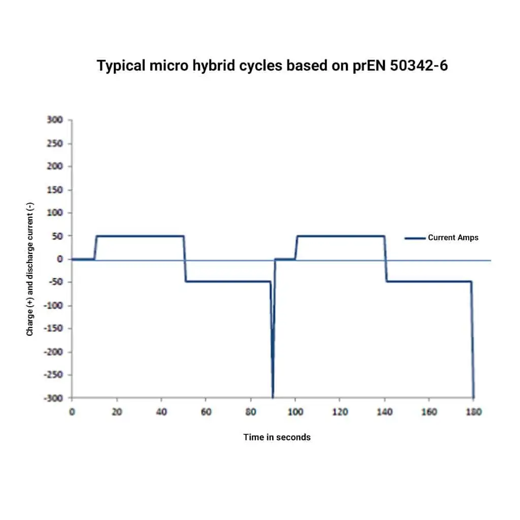
This was a major problem for the battery and the automotive industry and in 2015 a new standard test was added to the European Norm 50342 -6. which was a micro-hybrid endurance test for starter batteries. The basic principle of the test is shown schematically in Fig.1. Here it can be seen that the periods where the battery is being discharged and charged is a simulation of a car on a journey in a congested or built-up area such as a town or city.
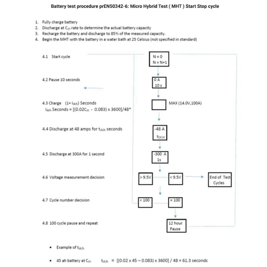
The next period is a couple of seconds discharge at 300 amps which simulates the engine starting current load on the EFB battery. This whole cycle is repeated continuously. Without getting into the absolute test procedure, it can be seen that this test is designed to simulate urban driving. The minimum number of these cycles that a battery should be able to perform is 8,000. Fig. 3 is an extract from the provisional standard pr50342-6, which has now been replaced by the approved version.
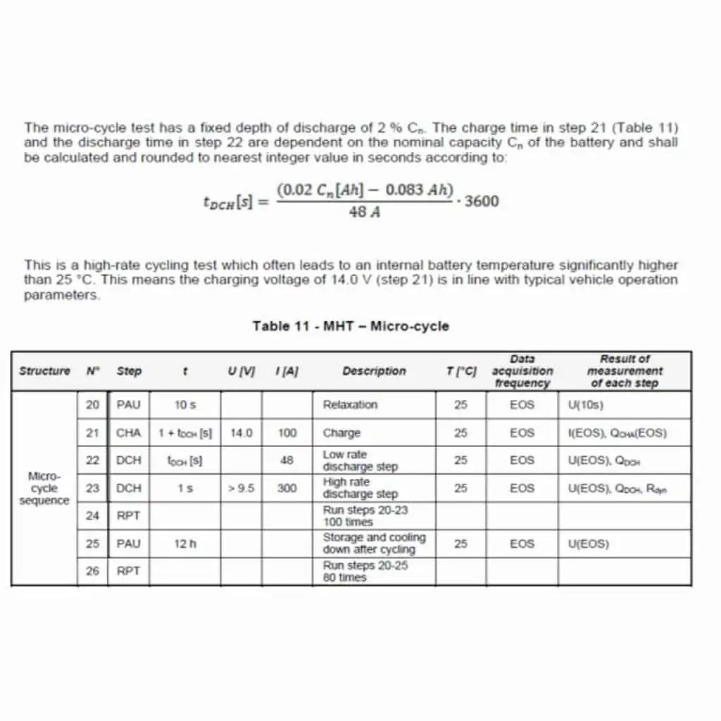
Fig. 3 is an extract from the provisional standard pr50342-6, which has now been replaced by the approved version.
How is EFB battery different from a flooded battery?
The primary function of the test is to highlight the effect on SLI batteries of a progressive rundown of a battery’s State of Charge (SoC) due to frequent discharges when the vehicle has stopped and inadequate recharging during the driving time between stops. In general, the rundown of the battery has catastrophic consequences and failure could occur within months due to plate sulfation, PSoC effects such as active material degradation and electrolyte stratification resulting in grid corrosion and paste shedding.
It has to be stressed that this is a simulation. However, it highlights the need to have a EFB battery that can absorb energy in a short time frame to replace the energy removed. Clearly, in absolute terms, the ability to replenish the energy used by a EFB battery in a start-stop vehicle depends on external factors. Some examples are: which country that you inhabit, whether you drive in a city or countryside, whether it is mid-winter in Moscow with full heat and light being used, or France in spring with no lights, heat or A/C is in operation.
The fundamental question is: with a EFB battery start-stop vehicle, how can you get enough charge into the EFB battery during the time available to at least replace the energy taken out?
We know that the alternator of the car and the engine management system are fixed in their operation this then leaves only the EFB battery to be modified. So, what properties of the EFB battery need to be adjusted to improve the absorption of current and prevent the damaging consequences of low SG, PSoC operation, stratification and PCL, listed earlier? At this point, we can list the battery characteristics which affect its current absorption and propensity to suffer from the listed effects.
These are:
- Internal resistance
- Battery capacity
- Active material
- Electrolyte mobility
- Grid alloy composition
In order to enhance battery performance, we can examine each of the above in order to make appropriate improvements.
Firstly, internal resistance: the higher this is the lower the current drawn at a fixed voltage recharge from the alternator I = V/R. The lower the current the lower the ampere-hours returned to the EFB battery during the periods when the car engine is running. In the first start-stop automobiles the EFB battery was certainly undercharged on the majority of short trips. This soon led to early battery failure with high rates of a warranty return. Internal resistance is a function of battery design, materials used and the production processes used in its manufacture
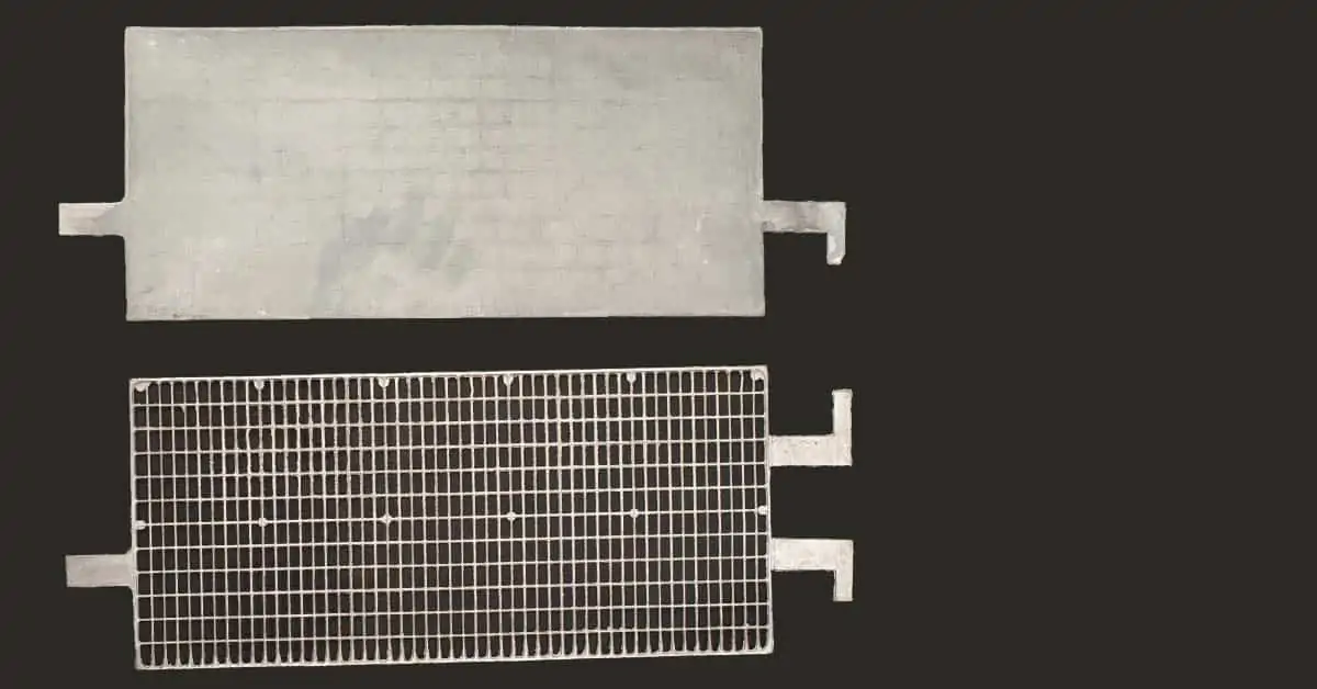
The design aspects include that of the grid, which if correctly shaped, can minimise the current collecting path. The total surface area of the plates is another important feature: the higher area the lower the battery resistance. Generally, more and thinner plates will maximise the conducting area. The cross-sectional area and quality of all the metal joints i.e. intercell welds, lug strap joints and take-off/terminal fusions will all contribute to the total internal resistance of the EFB battery . Cross-sectional areas of fused, welded areas should be maximised to provide the lowest metallic resistivity of components.
EFB Battery Life. How to enhance EFB Battery properties?
- Some aspects of lead acid battery manufacturing such as the paste mixing and curing steps require strict process controls. Temperature control is of critical importance in producing the optimum crystal structure in the pre-formed active material (AM). Higher processing temperatures promote the larger sized tetrabasic sulphate whose lower surface area reduces the charge acceptance properties of the AM and therefore the effectiveness of the EFB battery in start-stop operation.
- The EFB battery capacity is another important factor in determining the rate of current absorption. The higher the capacity, the higher the current drawn at any particular state of charge. The capacity is related to the area of the active material in the plates (mentioned above). Increasing the capacity gives a lower IR with a higher current draw than a lower capacity battery when charging at a fixed voltage.
Again, this means more capacity is returned to the EFB battery when the engine is running. It also gives the advantage of not discharging too deeply during a cyclic operation and thereby maintaining a higher state of charge (SOC) during its lifetime. The advantage of a higher SOC is that the battery is less likely to suffer from electrolyte stratification and the subsequent corrosion damage which that would cause.
- Active material efficiency is another factor which is related to battery failure. Improvements in charge acceptance can be made by additives, principally carbon in several forms, in the negative active material (NAM). There is a lot of speculation about the role of carbon, and many additive companies have their own proprietary product. These range from carbon nanotubes to flaky graphite, and all have the property of improving the efficiency of the active material in accepting a charge.
Again, this is a positive gain for batteries used for start-stop applications. EFB flooded batteries and increasingly, AGM batteries are raising the carbon content of their NAM. Use of a higher capacity flooded battery would help to prevent stratification by reducing the depth of discharge during normal operation This, in turn, means that the EFB battery is less likely to suffer from the damaging separation of dense and low SG acid during charge-discharge cycling.
- Electrolyte mobility refers to the ability of the electrolyte to move in the EFB battery . Flooded designs have the maximum mobility, whilst AGM and GEL variants of lead-acid batteries have little or no mobility. In these cases, the electrolyte is said to be immobilised. Putting aside the benefits of gas recombination, and therefore negligible water loss inherent in these designs, they confer the benefit of minimising or preventing electrolyte stratification due to deep discharge cycling.
- The materials, particularly the lead alloy used to manufacture the grid, have a significant impact on the internal resistance (IR) of the EFB battery . Use of lead-calcium instead of lead-antimony will give a lower resistivity, primarily because the amount of secondary alloying elements is a lot smaller. Great care has to be taken when choosing a suitable alloy, as the casting methods and processing controls need to be tailored to particular alloy combinations.
Incorrect grid processing can result in some of the ingredients in the grid alloy being removed, either by precipitation or by oxidation in the molten state. These losses can have a serious impact on the corrosion and creep resistance of the grid, which can lead to severe grid growth and penetrating corrosion which contributes to early EFB battery failure.
So far there have been a lot of requirements listed to produce the optimal EFB battery for start-stop use. Initially, the response from automobile OEMs was to use an AGM design of EFB battery which generally has a lower IR due to its grid alloy and slight oversizing to prevent over-discharge. It was also thought to reduce the incidence of stratification because of the immobility of the electrolyte. However, reducing cost was also a major factor for OEMs in finding a battery suitable for this application. The most favoured and perhaps most effective solution currently available in the Enhanced Flooded Battery (EFB battery).
So just what is an EFB?
The blog so far has described the problems of a micro-hybrid environment for an SLI lead acid battery. The causes of failure are almost invariably linked to the EFB battery’s inability to absorb charge quickly enough to replace the energy removed when an automobile engine is standing idle. This is also the cause of electrolyte stratification which plays a significant role in shortening SLI battery life in start-stop vehicles. The EFB solution provides most of the characteristics that a EFB battery needs to significantly improve charge acceptance. The charge acceptance for an SLI EFB battery in operation is often referred to as the Dynamic Charge Acceptance or DCA.
A brief summary of the EFB characteristics:
- Low internal resistance by better grid design and use of low resistance alloys (Pb/Sn/Ca ternary).
- Lower internal resistance by increasing plate area (thinner plates).
- Higher capacity (bigger EFB battery ) to increase the magnitude of the current drawn at fixed voltage recharge and limit the depth of discharge to both prevent electrolyte stratification and increase cycle life.
- Enhanced active material (generally carbon-based additives) to improve the charge acceptance of the battery.
These measures result in a flooded EFB battery which has a higher capacity (generally bigger) than standard batteries, has advanced lead alloy grids, a higher plate area and carbon enriched active material. This is, at present, the favoured design for SLI batteries in start-stop vehicles. It is favoured primarily because it is cheaper than an AGM version. AGM versions also tend to have around 15% lower capacity than a similarly sized flooded version. This means a higher DoD in operation which results in lower cycle life. Surprisingly, AGM designs can also suffer from electrolyte stratification if the DoD on cycling is around 80%.
It is of critical importance to understand which type of battery to purchase if (and definitely when), the battery fails on your start-stop vehicle. If you need help with this, then please feel free to contact Microtex who have the experience and knowledge to guide you in your battery purchase. In fact, if you have any battery issues with which you need help or guidance, Microtex, for the most part, will be your one-stop-shop for battery advice and products.