How Solar Photovoltaic System works?
The large magnitude of Sun’s heat energy makes it a highly appealing source of energy. This energy can be directly converted to direct current electricity and heat energy. Solar energy is clean, abundant and inexhaustible renewable energy source available on the earth. Solar panels or Solar photovoltaic systems using panels (SPV panels) are arranged on rooftops or in solar farms in such a way that the solar radiation falls on the solar photovoltaic panels to facilitate a reaction that converts sun’s light radiation into electricity.
Solar energy can be used to power a single building or it can be used on an industrial scale. When it’s used on a small scale, extra electricity can be stored in a battery or fed into the electricity grid. Solar energy is boundless and the only limitation is our ability to convert it to electricity in a profitable way. Tiny solar photovoltaic panels power calculators, toys and telephone call boxes.
Solar photovoltaic system definition
A solar photovoltaic system converts solar energy into electrical energy just as a battery converts chemical energy into electrical energy or an automobile engine converts chemical energy into mechanical energy or an electric motor (in an electric vehicle, EV) converts electrical energy into mechanical energy. An SPV cell converts solar energy into electrical energy. A solar cell does not produce electricity by using the sun’s heat, but the incident light rays interact with the semiconductor materials to produce electricity.
Electricity may be defined as the flow of electrons. How do Solar photovoltaic systems create this flow? Generally, energy has to be supplied to move electrons away from the nucleus of atoms. The valence electrons (that is, those in the outer shell of the atom) have the highest energy levels of the electrons that are still bound to their parent atoms, (as they are far away from the nucleus, compared to electrons in the inner shell). Additional energy is required to completely remove an electron from the atom, so, free electrons have higher energy levels than valence electrons.
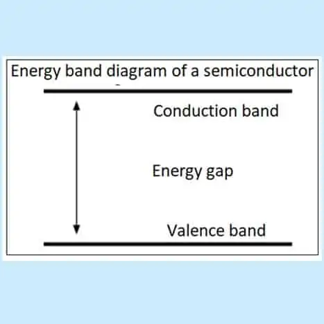
The figure above depicts an energy band diagram, which shows two energy levels, a valence band and a conduction band. Valence electrons are located in the valence band and the free electrons in the higher conduction band. In semiconductors, there is a gap between the valence and conduction bands. So energy must be supplied for valence electrons to go to the conduction band. This means that energy must be supplied to remove valence electrons from their parent atoms to become free electrons.
What are Solar Photovoltaic systems?
When pure silicon is at a temperature of 0 K (0 degree Kelvin is – 273°C ), all the positions in the outer electron shells are occupied, due to the covalent bonds between atoms and there are no free electrons. Therefore the valence band is completely full and the conduction band is completely empty. Though the valence electrons have the highest energy, they require the least energy to remove from the atom (ionization energy). This can be illustrated with an example of a lead atom. Here the ionization energy (of a gaseous atom) of first electron removal is 716 kJ/mol and that required for the second electron is 1450 kJ/mol. Equivalent values for Si are 786 and 1577 kJ/mol.
Each electron moving to conduction band leaves a vacant site (termed hole) in the valence bond. This process is called the electron-hole pair generation. A hole in a silicon crystal can, like a free electron, move about the crystal. The means by which the hole moves is as follows: An electron from a bond near a hole can easily jump into the hole, leaving behind an incomplete bond, i.e., a new hole. This happens fast and frequently-electrons from nearby bonds change positions with holes, sending holes randomly and erratically throughout the solid; the higher the temperature of the material, the more agitated the electrons and holes and the more they move.
The generation of electrons and holes by light is the central process in the overall Photovoltaic effect, but it does not itself produce a current. Were there no other mechanism involved in a solar cell, the light-generated electrons and holes would wander about the crystal randomly for a time and then lose their energy thermally as they return to valence positions. To exploit the electrons and holes to produce an electric force and a current, another mechanism is needed – a built-in “potential” barrier.* A photovoltaic cell has two thin wafers of silicon sandwiched together and attached to metal wires.
During the manufacture of the ingots, the silicon is pre-doped before slicing and shipping. Doping is nothing but adding impurities into the crystalline silicon wafer to make it electrically conductive. Silicon has 4 electrons in the outer shell. These positive (p-type) doping materials are invariably Boron, which has 3 electrons (trivalent) is called positive-carrier (Acceptor) Dopant. The negative (n-type) dopant is phosphorus, which has 5 electrons (pentavalent) is called the negative-carrier (Donor) Dopant
A photovoltaic cell contains a barrier layer that is set up by opposite electric charges facing one another on either side of a dividing line. This potential barrier selectively separates light-generated electrons and holes, sending more electrons to one side of the cell, and more holes to the other. Thus separated, the electrons and holes are less likely to rejoin each other and lose their electrical energy. This charge separation sets up a voltage difference between either end of the cell, which can be used to drive an electric current in an external circuit.
When a photovoltaic cell is exposed to sunlight, bundles of light energy known as photons can knock out some of the electrons from the bottom P-layer from their orbits through the electric field set up at the P-N junction and into the N-layer. The N-layer, with its surplus of electrons, develops a stream of an excess of electrons, which produces an electric force to push the additional electrons away. These excess electrons, in turn, are pushed into the metal wire back to the bottom P-layer, which has lost some of its electrons. Thus the electrical current will continue to flow till the sun rays are incident on the panels.
Solar Photovoltaic system can be only slightly energy efficient
Today’s Solar photovoltaic system cells convert only about 10 to 14 per cent of the radiant energy into electrical energy. Fossil fuel plants, on the other hand, convert from 30-40 per cent of their fuel’s chemical energy into electrical energy. Electrochemical power sources conversion efficiency is much higher up to 90 to 95 %.
What is Conversion Efficiency of Solar Photovoltaic System?
Efficiency of a device = Useful energy output / Energy input
In the case of Solar photovoltaic system the efficiency is about 15%, which means that if we have a cell surface of 1 m2 for every 100 W/ m2 of incident radiation, only 15 W would be delivered to the circuit.
SPV cell efficiency = 15 W/ m2/ 100 W/ m2 = 15 %.
In the case of lead-acid batteries we can differentiate two types of efficiency, the coulombic (or Ah or ampere-hour) efficiency and energy (or Wh or watt hour) efficiency. During a charging process which converts electrical energy into chemical energy, the Ah efficiency is about 90 % and the energy efficiency is about 75 %
Solar Photovoltaic system working priniciple
Manufacture of Solar Photovoltaic system cells
The raw material is the second most abundantly available quartz (sand). Quartz is a widely distributed mineral. It has many varieties that consist mainly of silica or silicon dioxide (SiO2) with small fractions of impurities like lithium, sodium, potassium and titanium.
The process of making a solar cell from a silicon wafer involves three types of industries
a.) Industries producing solar cells from quartz
b.) Industries producing silicon wafers from quartz and
c.) Industries producing solar cells from silicon wafers
How are silicon wafers made in Solar Photovoltaic system?
As a first step, pure silicon is produced by reduction and purification of the impure silicon dioxide in quartz. Czochralski (Cz) process: The PV industry currently uses two primary routes for converting raw polysilicon feedstock into finished wafers: the monocrystalline route using the Czochralski (Cz) process, and the multi-crystalline route using the directional solidification (DS) process. The primary differences between these two approaches are in how the polysilicon is melted, how it is formed into an ingot, the size of the ingot, and how the ingots are shaped into bricks for wafer slicing
- Czochralski (Cz) process: The Cz method creates a cylindrical ingot, and this is followed by multiple steps of band and wire sawing to produce wafers. For a typical 24-in diameter crucible loaded with an initial charge weight of about 180 kg, approximately 35 hours are required to melt the polysilicon in a Cz crucible, dip the seed crystal into the melt, and pull out the neck, shoulder, body, and end cone. The result is a cylindrical Cz ingot with a mass of 150–200 kg. To leave metals and other contaminants behind, it is necessary to leave 2–4 kg of pot scrap in the crucible.
- Directional solidification (DS) process: Multi-crystalline DS wafers are fabricated from shorter but much wider and heavier ingots— around 800 kg—that assumes a cube shape when the polysilicon is melted within a quartz crucible. After the polysilicon is melted, the DS process is induced by creating a temperature gradient where the bottom surface of the crucible is cooled at a certain rate. Similar to Cz ingots, sections of DS ingots produced during cropping and squaring can be remelted for later ingot generations. In the case of DS ingots, however, the topmost section is usually not recycled owing to the high impurity concentration.
Because the process begins with a cube-shaped melting crucible, DS ingots and wafers are naturally square in shape, making it easy to create multi-crystalline based cells that can occupy essentially the entire area within a complete module. About 76 hours are required to produce a typical DS-silicon ingot, which is sawn into 36 bricks from a 6 x 6 cut-out. A typical finished brick has a 156.75 mm x 156.75 mm full-square cross-section (246 cm2 of surface area) and a height of 286 mm, which yields 1,040 wafers per brick when the wafer thickness is 180 µm and there is 95 µm of kerf loss per wafer. Thus, 35,000–40,000 wafers are produced per DS ingot.
Bibliography
1. https://sinovoltaics.com/solar-basics/solar-cell-production-from-silicon-wafer-to-cell/
2. Basic PV Principles and Methods NTIS USA 1982 https://digital.library.unt.edu/ark:/67531/metadc1060377/
3. http://www.madehow.com/Volume-1/Solar-Cell.html#:~:text=To%20make%20solar%20cells%2C%20the,carbon%20dioxide%20and%20molten%20silicon.
4. Woodhouse, Michael. Brittany Smith, Ashwin Ramdas, and Robert Margolis. 2019. Crystalline Silicon Photovoltaic Module Manufacturing Costs and Sustainable Pricing: 1H 2018 Benchmark and Cost Reduction Roadmap. Golden, CO: National Renewable Energy Laboratory. https://www.nrel.gov/docs/fy19osti/72134.pdf. pp. 15 et seq
Different types of solar photovoltaic systems
As fossil fuel prices continue to rise and emission standards continue to get stricter around the globe, the demand for renewable energies like solar power and wind generation and energy storage solutions will continue to rise.
The term solar refers to the sun. Solar batteries are those which are used in storing the energy converted from solar irradiation or light energy into electricity using solar cells (also called solar photovoltaic cells, or PV cells) through the photovoltaic effects. They do not involve chemical reactions as in batteries. The PV cell is composed of semiconductor material, which combines some properties of metals and some properties of insulators, which makes it capable of converting light into electricity.
When light is absorbed by a semiconductor, photons of light can transfer their energy to electrons, generating a flow of electrons. What is electrical current? It is the flow of electrons. This current flows out of the semiconductor to output leads. These leads are connected to the battery or grids through some electronic circuits and inverter to control and generate alternating current.
Methods of using solar photovoltaic system power
Stand-alone (or Off-Grid) SPV system:
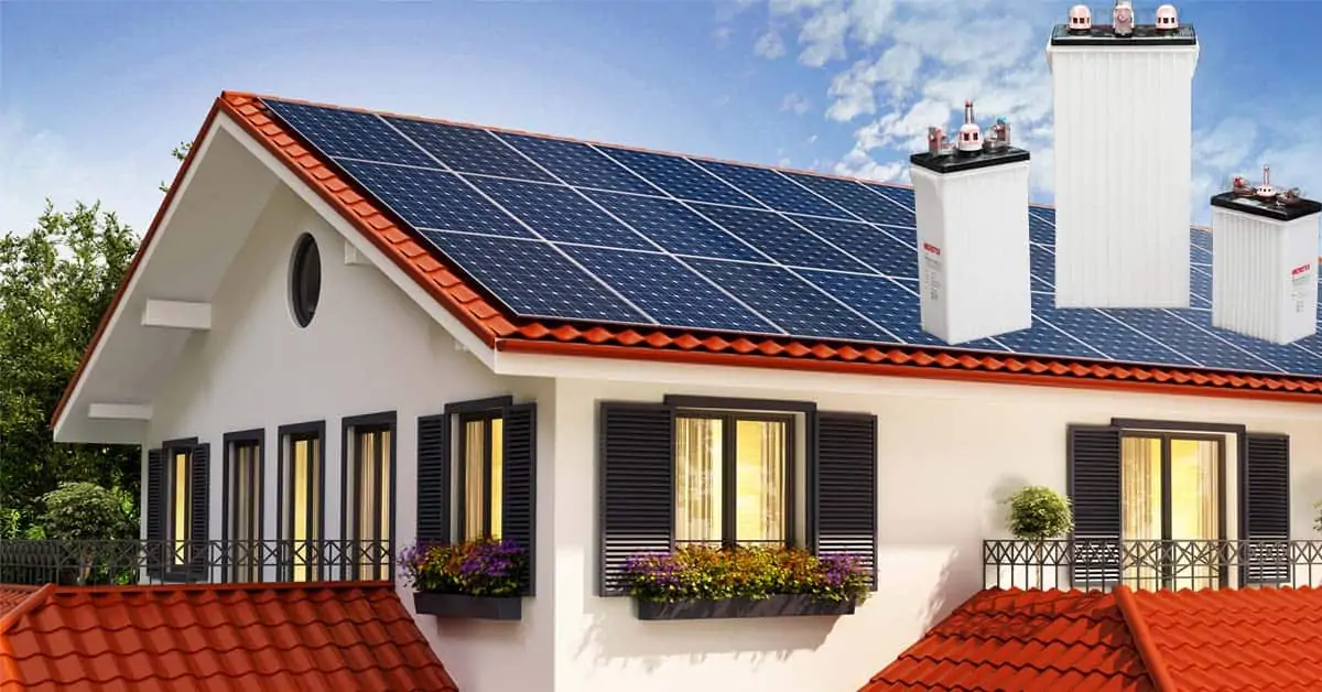
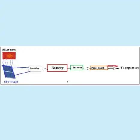
Here the solar power is used for a single home or an industrial unit or small community. The power produced by the solar panels is sent to the battery via electronic controller and batteries store the energy. The DC from the battery is inverted to AC; the electrical loads draw their electricity from these batteries. Normally, a 1 kW rooftop solar system requires 10 sq. metres of shadow-free area. Actual sizing, however, depends on local factors of solar radiation and weather conditions, the efficiency of the solar module, the shape of the roof etc.
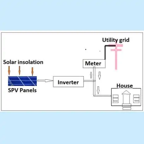
Straight grid-tied Solar Photovoltaic system (or Grid-tied system)
In a straight grid-tied system (or Grid-tied system), the SPV panels will be connected to the public power distribution lines through controller and energy meter. Here no batteries are used. The electricity is used first to power the home’s immediate electrical needs. When those needs are met, the additional electricity is sent out to the grid through the energy meter. With a grid connect solar power system when the house requires more power than what the solar panels are producing then the balance of electricity required is supplied by the utility grid.
So, for example, if the electrical load in the house is consuming 20 amperes of current and the solar power can generate only 12 amperes, then 8 amperes would be drawn from the grid. Obviously, at night all of the electrical needs are supplied by the grid because with a grid connect system you do not store the power you generate during the day.
One disadvantage of this type of system is that when the power goes out, so does the system. This is for safety reasons because linemen working on the power lines need to know there is no source feeding the grid. Grid-tied inverters have to automatically disconnect when they don’t sense the grid. This means that you cannot provide power during an outage or an emergency and you can’t store energy for later use. You also can’t control when you use the power from your system, such as during peak demand time.
Grid interactive or Grid-tied (hybrid) Solar Photovoltaic system
There is yet another system where we can supply to the grid system. We can earn money or get back the energy supplied by us whenever needed.
Solar Photovoltaic system without battery storage - Grid interactive or Grid-tied (hybrid)
These SPV systems generate solar electricity and supply in-house loads and to the local distribution system. This type of SPV system components is (a) SPV panel and (b) Inverter. The grid-connected system is similar to a regular electric powered system except that some or all of the electricity comes from the sun. The drawback of these systems without battery storage is that they do not have a power supply during the power outages.
Advantages grid-tied (hybrid) Solar Photovoltaic system without battery storage
It is the least expensive system with negligible maintenance
If the system produces more power than the in-house need, then the extra energy is exchanged with the utility grid
Grid-direct systems have a higher efficiency because batteries are not involved.
Higher voltage means a smaller wire size.
The approximate cost of grid-connected rooftop solar systems for FY 2018-19 varied from Rs. 53 per watt – Rs. 60 per watt.

Grid interactive or Grid-tied (hybrid) Solar Photovoltaic system with battery storage
This type of Solar Photovoltaic system is connected to the grid and can qualify for state incentives, while also lowering your utility bill. At the same time, if there’s a power outage this system has back up power. Battery based grid-tied systems provide power during an outage and energy can be stored for use in an emergency. Essential loads such as lighting and appliances are also having back up power when the power is out. One can also use energy during peak demand times because the energy has been stored battery bank for later use.
The main drawbacks of this Solar Photovoltaic system are that the cost is higher than the basic grid-tied systems and is less efficient. There are also added components. The addition of the batteries also requires a charge controller to protect them. There must also be a sub panel that contains the important loads that you want to be backed up. Not all the loads that the house uses on the grid are backed up with the system. Important loads that are needed when there is a power outage. They are isolated into a back-up sub-panel.