Introduction to electrical terms & electrochemical terms
Electrical engineering is a branch of engineering that deals with the generation, distribution, and use of electrical energy.
Electrochemistry is the branch of Chemistry from which we learn the reactions occurring as a result of the passage of electricity (direct current) and the reverse of generation of direct current by reversing the reactions (batteries) and all other processes like electrochemical production of gases (like hydrogen), metals like sodium, magnesium, etc., organic, and inorganic chemicals, metal finishing processes like electroplating, anodic phosphating, and other innumerable techniques.
Electro-technology is concerned with the utilization and practical application of electricity.
The following is a comprehensive treatment of the terms employed in the battery parlance:
Lead acid battery
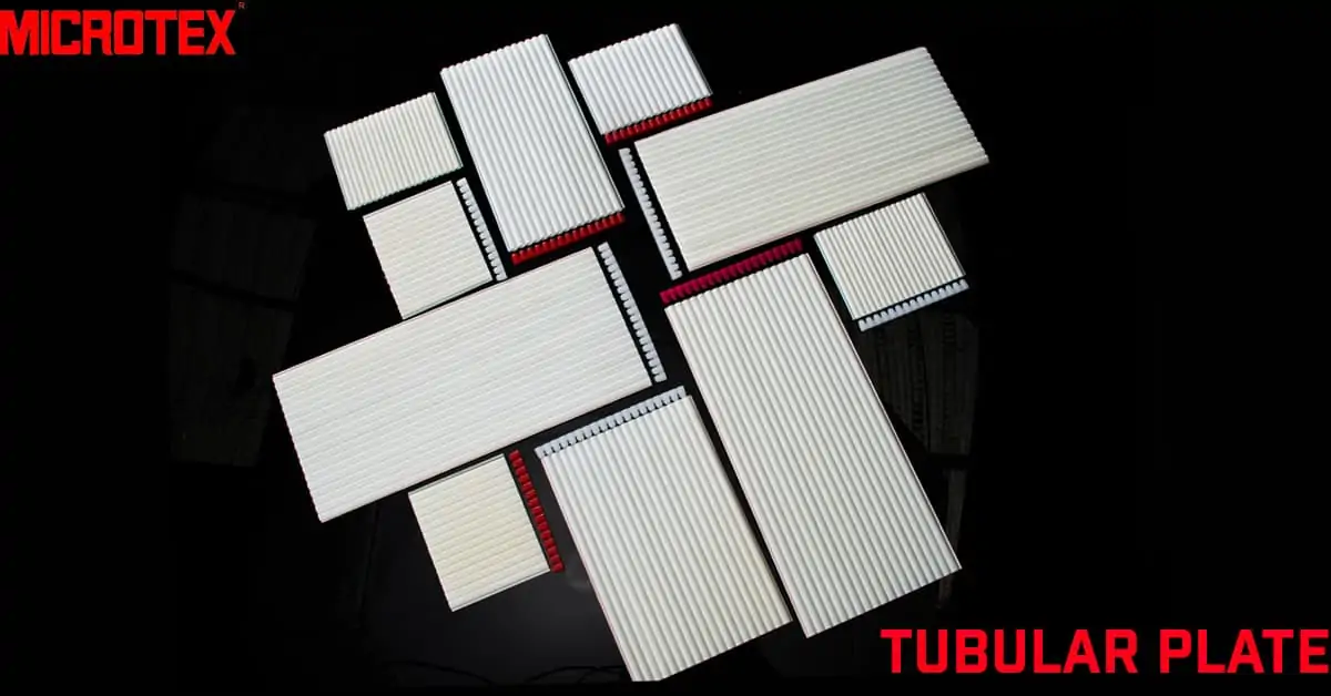
The lead-acid battery is a rechargeable electrochemical system, more than 160 years old, and evolved from a heavy, cumbersome, and ugly black box to present-day attractive products. A rechargeable battery is also known as an accumulator, secondary battery, or storage battery To start with, there was only what we today term as flooded cells. Slowly the battery evolved into flat plate type, tubular plate type, and valve-regulated (VR) type. The latter again developed into absorptive glass mat (AGM) and gelled electrolyte types. The latest developments are in carbon-enhanced lead-acid batteries.
The terms used in battery industries and battery research are given below:
Activation:
This term refers to the method of making a cell come to life.
The method of activation maybe by adding a suitable electrolyte into the cell compartments. A typical example is a dry-charged lead-acid battery, activated by pouring dilute sulphuric acid as recommended by the manufacturer. Or, as in the case of silver oxide-zinc (AgO-Zn) reserve cells, an aqueous solution of potassium hydroxide (KOH) is added when required.
Reserve cell
A reserve cell has the electrodes assembled with the separator but without an electrolyte. In one method of activation of reserve cell, the cell elements may be immersed in the electrolyte. The most familiar example is sea-water-activated marine batteries used to guide boats and ships. They are magnesium-silver chloride (Mg-AgCl) battery, magnesium-cuprous chloride (Mg-CuCl) battery, magnesium-lead chloride (Mg-PbCl2) battery, silver oxide-zinc (AgO-Zn) batteries, etc. When required to be activated, these cells are filled with a suitable electrolyte (such as an aqueous solution of KOH in the case of AgO-Zn reserve cells) or, as in the case of Mg-activated batteries, allowed to come into contact with the seawater, which acts as the electrolyte (i.e., an aqueous sodium chloride solution).
The latter type of battery acts as a power source for sonobuoys and marine markers.
In the Mg-AgCl cell, the total reaction is given as
Mg + 2AgCl → MgCl2 + 2Ag.
One can see that the reaction product of the cathode active material (silver chloride) is highly conducting metal, silver, and so the conductivity of the system increases as the discharge proceeds.
Similarly, in Mg-CuCl cell, the metal copper is produced on the cathode:
Mg + 2CuCl → MgCl2 + 2Cu
Also, there are remotely activated reserve cells that use some sort of activation mechanism so that the electrodes are allowed to come into contact with the electrolyte. Such types of cells are used in military war systems.
Thermally activated cells
Thermally activated cells are brought into a functional mode by heating, whereby the electrolyte melts, and the cell becomes active [Charles M. Lamb, Chapter 36, Thermal Batteries, in Handbook of Batteries, fourth edition (Ed.) Thomas B. Reddy, McGraw-Hill, New York, 2011, pp. 1232 – 1251. Crompton, T.R., Battery Reference Book, Second Edition, SAE International, P.A., USA,. 1996, pp 186-189].
Electric Current
When a suitable resistance (load) is connected to the two terminals of a battery, the free electrons from the metallic anode (for example, the lead electrode in a lead-acid cell) begin to move, attracted by the positive terminal of the cell. We say the current is flowing in the wires. The force behind the movement is the voltage or the potential difference of the cell. Thus, current can be defined as a flow of charged particles such as electrons (and ions).
The medium of flow for electrons is mostly metallic conductors like copper or aluminium wires, or it may be what we call a “hole” in semiconductors (electronic conductors). In the case of electrolytic conduction as in acid, alkali, or a salt solution, the charged particles (called “ions”) like hydrogen ion or proton (H+) or hydroxyl ion (OH), potassium ion (K+), sulphate ion (), bisulphate ion (H), lithium-ion (Li+), etc. are the charge carriers.
Ampere
is the SI unit or International System of Unit (or in the French language Systéme International de Unités) for current.
Ampere (SI symbol “A”) is the flow of current through a conductor at the rate of one ampere-second (termed a “coulomb”, SI symbol = C). Coulomb = A*s = As.
The higher unit is ampere-hour (Ah). The Faraday constant is equal to 96485 (or 96500) C per mole (=26.8 Ah per mole). One F is the charge carried by a mole of elections.
Watt-hour is obtained by multiplying voltage and ampere-hour:
Wh = Voltage * Ah
How do we arrive at the Faraday constant, F?
By definition, F is the total charge carried by one mole of electrons. Mole is defined as 6.023 *1023 particles (to be exact, it is 6.02214076 *1023). We say that there is an Avogadro number of particles in each mole of any substance. The particles may be atoms, molecules, or ions. Therefore, the total charge carried by one mole of electrons is equal to the charge of an electron multiplied by the Avogadro number of electrons.
The charge carried by an electron is 1.602 * 10-19 Coulombs. (To be more accurate 1.602176634 * 10-19)
Therefore,
F = the total charge carried by one mole of electrons
= [(1.602 * 10-19 Coulombs) * (6.023 *1023)]
= 96485 Coulombs per mole (also written as 96485 Coulombs/mole or 96485 Coulombs mole-1)
What is the practical applicability of the Faraday constant?
The most common application of F is in the calculations in electrochemical reactions. One can obtain the amount of a chemical deposited or discharged by the Faraday Constant
Let us assume that we have passed 0.5 F (or 13.4 Ah) of electricity (= Q) in a cell used for plating silver from silver nitrate solution. The first of Faraday’s laws of Electrolysis states that for an electrochemical reaction of a chemical having a mass of m gets deposited or discharged is proportional to the quantity of electricity that is passed through the cell.
m α Q (Q = current *time = It)
m = EQ where E is the constant of proportionality named electrochemical equivalent
m = E*It (The value of E for silver is 107.87/96485 g/ F = 0.001117998 g /C)
= 0.001117998 g per Coulomb *13.4 Ah
= 0.001117998 * 13.4*3600 (Converting Ah into As or coulomb)
= 53.935 g
Hence, the mass of silver deposited by 0.5 F is 53.935 g.
For an example from a lead-acid cell:
In an electrochemical reaction, if one electron is involved, then one Faraday of electricity can be transferred.
We can find out how much electricity can be produced by 1 mole of PbO2. Because 2 electrons are involved in the lead-acid cell reactions (Pb4+ → Pb2+ or Pb → Pb2+), 2 F electricity can be produced theoretically by 1 mole of PbO2 or 1 mole of lead during a discharge reaction. (We can also state that 2 Faraday electricity will be required theoretically for converting 1 mole of PbSO4 to 1 mole of PbO2 or 1 mole of lead during a charging reaction of the lead-acid cell). Molecular weight of PbO2 is 207+ (2*16) = 239.
239 g = 2*F per mole
= 2*26.8 Ah per mole = 53.6 Ah per mole.
Therefore, 53.6 Ah can be produced by one mole or 239 g of lead dioxide.
For 1 Ah we require 239/53.6 = 4.46 g of lead dioxide per Ah
This value is called the capacity density of lead dioxide.
[Hans Bode, Lead-Acid Batteries, John Wiley, New York, 1977, p.292.]
Specific capacity
The specific capacity of PbO2 is the reciprocal of capacity density = 1/4.46 = 0.224 Ah per gramme (224 Ah per kg)
Similarly, 53.6 Ah can be produced by 207 g of lead.
Hence the capacity density of lead = 207/53.6 = 3.86 g per Ah
The specific capacity of Pb is 1/3.86 = 0.259 Ah per gramme ((259 Ah per kg)
Capacity density
The capacity density of the electrolyte sulphuric acid (in terms of concentrated acid) is equal to
196.16/53.60 = 3.66 g per Ah and the specific capacity is equal to 1/3.66 = 0.2732 Ah /g (273.2 Ah per kg). These figures refer to the 98.3% concentrated sulphuric acid, which is never used in practical lead-acid cells.
For the practical specific gravity acid 1.280, which contains 38 % concentrated acid by mass, the value for specific capacity will be 1280 g * 0.38 (% in fraction) = 486.4/3.66 = 133 Ah per litre (called electrochemical equivalent) or 1000 g * 0.38 = 380/3.66 = 104 Ah per kg
Now that we have learned about the specific capacity of active materials, we go further and learn about the theoretical specific energy of the cell.
The specific energy lead-acid cell
The omnipresent lead acid will be taken as the first example for the calculation of theoretical specific energy.
The reaction is written down, and the molar values of the reactants are calculated. We need not worry about the products. For a lead-acid battery, the reaction is:
PbO2 + Pb + 2H2SO4 ⇄ 2PbSO4 + 2H2O Eº = 2.04 V.
Σ moles = 239 +207+ 2*98 in g
= 0.642 kg
Theoretical Specific Energy = 26.8 × (nE/Σmoles) Wh/kg
= 26.8*(2*2.04/0.642) Wh/kg
= 26.8015*(6.3551) Wh/kg
= 170.3 Wh/kg.
The specific energy can also be calculated as given below for lead-acid cell: [Tobias Placke, J Solid State Electrochem (2017) 21:1939–1964],
Specific energy of a cell =
___________________1_______________________
1/Sp EnergyN + 1/Sp EnergyP + 1/Sp EnergyAcid
=1[1/(224*2.04) + 1/(259*2.04) + 1/(273*2.04)]
= 1[(1/457) + (1/528) + (1/557)]
= 1/(0.002188 + 0.001893 + 0.001796)
= 1/0.005877
= 170 Wh/kg
But the theoretical specific energy of a cell is very difficult to achieve. In the case of the lead-acid cell, about 35 to 40 % can be achieved.
Energy density
Energy density defines the energy available from the battery in terms of its volume, the unit being Wh per litre. The specific energy and energy density of some of the battery systems are given below:
Table 1. Specific energy and energy density of some battery systems
System | Voltage (V) | Specific energy (Wh/kg) | Energy density (Wh/L) |
Lead-acid | 2.1 to 1.8 | 40 | 80 |
Ni-Cd | 1.25 to 1 | 30 to 40 | 80 to 100 |
Ni-Fe | 1 .25–1.05 | 30 | 55 |
Ni-MH | 1.25–1.10 | 100 | 430 |
Li (LCO) | 3.7 | 200 | 570 |
Alternating current (AC) or direct current (DC)
Current can be either alternating current (AC) or direct current (DC)
The difference between the two types of current lies in the direction of flow. In AC, the current is bidirectional, while it is unidirectional in DC, as shown in the figures.
In AC, the current and voltage vary continuously at any moment. The oscillation occurs from the maximum peak to the minimum along a common reference point.
In AC, the polarity of the current goes on changing, as shown in the figure. When a waveform completes two amplitudes (positive and negative), it is termed one “cycle” and comprises of an angular measure of 360°. The frequency of the wave is measured in cycles per second (cycles/s) and expressed in units of Hertz (Hz), f being the representing symbol. In India, the f value is 50, which means that the AC supplied has 50 cycles per second or 50 Hertz.


Because the direction of the direct current does not change, the polarity of the voltage remains the same.
Alternators, rotor, stator
AC generators are called alternators and work on the principle of electromagnetic induction. It is made up of a coil (a rotating field winding called the rotor) that rotates inside a stationary magnetic field (a stationary induction winding called the stator), as in a water turbine (hydroelectric generation plant) or a steam or wind turbine or in an automobile. The rotation causes variation in the magnetic field lines affecting the coil, which induces an electric current in the coil. The rotation of the coil causes polarity reversal of the magnetic field, and so the current and voltage in the coil change their direction periodically.

DC is generated by an electrochemical power source or a DC generator. DC generators also work on the principle of electromagnetic induction. In a DC generator, the armature rotates, and the field system is stationary, which is just the opposite of alternators which we discussed a little earlier
Another way is to rectify AC to produce DC by using a rectifier. In simple words, rectification is the process of conversion of a bidirectional current (AC) into a unidirectional current (DC).
The reverse phenomenon, i.e., conversion of DC to AC, is done by an inverter.
Rectifier
The rectifier employs an electrical circuit for the conversion of AC to DC. The most important component is a diode, which allows the current to pass only in one direction. It either blocks the reverse amplitude of AC or redirects it to a single direction, thus making it unidirectional DC.
Polarization
Polarization is a phenomenon that lowers the voltage due to the kinetics of the electrode reactions of an electrochemical cell. We say the electrodes are polarized. This may happen due to several causes.
Activation polarization (charge transfer overvoltage) The energy needed to activate the electron transfer reaction (also termed transfer polarization)
The resistance offered by the conducting components (electronic and electrolytic). IR drop
Hindrances due to ion transport processes, i.e., due to concentration gradients (Concentration polarization / Diffusion polarization).
Overvoltage
As a consequence of these reasons of polarization, the battery terminal voltage drops to some extent during a discharge, depending on the intensity of the current. This voltage drop is also termed “overvoltage”
This happens on both positive and negative electrodes and so total polarization is a result of this combination effect.
The drop will be positive for an anodic process (for example, the discharge reaction of the negative plate of a lead-acid cell), As a consequence, the voltage of this electrode will become more positive -0.35 V to ~ -0.340 V).
The drop will be negative for a cathodic process (for example, the discharge reaction of the positive plate of a lead-acid cell), As a consequence, the voltage of this electrode will come down and will become less positive (1.69 to 1.60 V).
In the case of the negative plate, the potential increases and moves towards zero voltage, and the other plate potential also similarly moves towards zero voltage. In other words, the two electrodes move towards each other and tend towards zero. As a consequence, a double decrease is experienced by the total cell voltage.
Active materials
The chemical entities in the electrodes (or plates) taking part in the energy production processes of the cell are called active materials. Some active materials and the systems in which they are employed are given below:
Table 2. Active materials of some battery systems
Cell chemistry | Negative active material (NAM) | Positive active material (PAM) | Electrolyte | Year of invention | Nominal Cell voltage (V) |
Lead-acid cell | Lead (Pb) | Lead dioxide (PbO2) | Aqueous sulphuric acid (H2SO4) solution | 1859 | 2.04 (2.15 to 1.75) |
Lithium-ion cell | Carbon (C) (graphite and amorphous carbon compounds) | LiCoO2 or LiMnO2 or LiFePO4. | A mixed solution of organic liquids containing the actual electrolyte salt♦ | Sony Corporation, Japan, 1991 (by a joint venture of Asahi Kasei and Toshiba in 1992) | 3.2 to 3.8 |
Nickel-cadmium cell | Cadmium (Cd) | Nickel oxy hydroxide (NIOOH) | Aqueous potassium hydroxide (KOH) or sodium hydroxide (NaOH) solutions | 1899 by Waldemar Jungner of Sweden | 1.33 V (1.3 to 1.0) |
Nickel-iron cell | Iron (Fe) | Nickel oxy hydroxide (NIOOH) | Aqueous potassium hydroxide (KOH) or sodium hydroxide (NaOH) solutions | 1901 Thomas Alva Edison, USA | 1.33 V (1.3 to 1.0) |
Nickel-Metal hydride cell | Hydrogen (from metal hydrides) | Nickel oxy hydroxide (NIOOH) | Aqueous potassium hydroxide solution (KOH) | Around 1986 First EV battery in 1993 | 1.35 V (1.3 to 0.8) |
Hydrogen-oxygen fuel cell | Hydrogen (supplied externally) | Oxygen (supplied externally) | Aqueous potassium hydroxide solution (KOH) | 1838 William Grove | 0.9 |
Zinc-air | Zinc (Zn) | Oxygen (O2) from atmosphere | Aqueous potassium hydroxide solution (KOH) | 1990 | (1.65) 1.15 |
Leclanché cell (Dry cell) | Zinc (Zn) | Manganese dioxide (MnO2) | Aqueous ammonium chloride solution (NH4Cl) | 1866 Georges Leclanché France | 1.6 (14 to 0.75) |
Alkaline MnO2 cell (e.g. “Duracell”) | Zinc (Zn) | Manganese dioxide (MnO2) | Aqueous potassium hydroxide (KOH) solution | 1960s L F Urry, Canada | 1.5 (1.5 to 0.9) |
Silver oxide –zinc cell | Zinc (Zn) | Silver oxide (AgO) | Aqueous potassium hydroxide (KOH) solution | 1950s Yardney Electric Corporation, USA | 1.85 (1.8 to 1.4) |
♦Mixtures of ethylene carbonate (EC) with dimethyl carbonate (DMC), diethyl carbonate (DEC), and ethyl methyl carbonate (EMC). Lithium salts such as lithium hexafluoro phosphate (LiPF6), lithium hexa fluoro arsenate (LiAsF6), lithium tetra fluoro borate (LiBF4), lithium perchlorate (LiClO4), lithium trifluoromethane sulphonate (LiCF3SO3), Lithium difluoro(oxalato) borate (LIODFB) etc., are the actual electrolytes (sustaining electrolyte salts)
It can be noted that all the negative active materials (NAM) are metals, the exception being hydrogen (a gaseous element) and carbon, a non-metal.
Positive active materials (PAM) are mostly oxides and mixed oxides, oxygen, and chlorine being gaseous elements. Other PAMs are halides, sulfides, etc.
Anions
Ions are charged particles formed from elements and compounds. Anions are negatively charged particles because they are formed when they gain electrons. They are formed mostly from nonmetals. Since they are charged negatively, they get attracted by anode or positive electrodes during an electrochemical reaction. They have one to three charges. They may be mono-atomic or poly-atomic. Examples are (perchlorate ion), (chloride ion), (Hexafluoro phosphate ion) (oxide ion), (phosphate ion). (sulphate ion).
Cations
Cations are positively charged particles because they are formed when they lose electrons. Since they are charged positively, they get attracted by cathode or negative electrodes during an electrochemical reaction. They are formed mostly from metals, hydrogen being an exception.
Li+ (lithium ion), H+ (hydrogen ion or proton), Pb2+ (lead ion bivalent), Al3+ (aluminium ion, trivalent),
Sn4+ (Tin ion, quadrivalent. stannic).
Ions can also be formed by more than two elements. Examples are
HCO3– (bicarbonate ion), MnO4– (permanganate ion), SCN(thiocyanate ion) Cr2O72- (dichromate ion)
An Electrolytic cell
The figure shows an electrolytic cell with anions and cations.
Anolyte and catholyte are those portions of the electrolyte that are adjacent to respective electrodes.

Aprotic solvent
A solvent that does not involve reactive hydrogen ions (as in water). It does not possess O-H or N-H bonds. These molecules cannot form hydrogen bonds among themselves but are capable of accepting hydrogen bonds from other molecules. But it may contain hydrogen atoms, as in the case of the acetone molecule, which does not possess an O-H group but has a carbonyl group (C=O) that can participate in hydrogen bonding.
Bipolar plate / Bipolar battery
A battery plate or electrode is an electrode whose one side has a positive active material and the other side forms the negative active material of the adjacent cell. The supporting base material is an electronic conductor, which both acts as a partition wall and an inter-cell connector. It, therefore, should be liquid-impermeable and so non-porous. The electronic conductor may be a carbon plate or a composite conducting polymer material
A bipolar battery contains bipolar plates in the middle cells and mono-polar plates in the extreme cells. A schematic of a bipolar plate and also a bipolar cell are shown in Figures 4 and 5.
It should be noted that there is no need for a separate partition wall and an inter-cell connector. Both these functions are satisfied by the central base plate. In addition, this central plate also acts as the grid.
Because of these reasons, the weight of the battery is very much lowered, and the current path is also significantly reduced, as can be seen from the figure of the bipolar cell.
There are true bipolar and quasi-bipolar or wrap-around plate batteries. In the former, the current flow is vertical to the plates, whereas in the other, it is longer. For more details, refer to the publication given below. [J.L.Arias, J.J, Roulette and E,D. Drake, J. Power Sources 40 (1992) 65]


P = Positive terminal or Positive plate
N =Negative terminal or Negative plate
S = Separator ICC = Intercell connectors
BPP = Bipolar plate
MP = Monopolar plate
Boost Charging
Boost charging is a quick and high-rate charging method used in an emergency when no other battery is available and the SOC is not enough for the emergency work. Such charges are also given at rest periods of traction batteries to prolong the period of use. The application of relatively high charge currents (~1.5 to 2 times the C5 charging rate) can bring the batteries to 80% in a short time.
Cadmium readings
Cadmium is a metal resembling zinc and is used to determine the individual electrode potentials of the lead-acid cell. The use of this electrode dates back to 1892 when Lucas used it in AFA -Varta [Hans Bode, Lead-Acid Batteries, John Wiley, New York, 1977. p 88]. An insulated cadmium rod (8 to 10 mm thick) with a flexible copper wire soldered to one end and the other end being open to access the electrolyte is termed a cadmium reference electrode.
The standard electrode potential (E° value) of this electrode is -0.402 V. The scientific notation is Cd/Cd2+.
A new electrode has to be soaked in the dilute sulphuric acid solution for 1 to several days before use to provide a sufficient corrosion layer on the electrode. The longer the soaking, the more accurate and reproducible the results would be. The electrode should be immersed in the cell electrolyte when taking the cadmium readings. The negative lead of the digital multimeter should always be connected to the cadmium reference electrode, and the positive lead to the terminal of the electrode for which we need the cadmium potential value.
After use, the electrode should be washed and stored dry. Again, when required for use, the electrode should be immersed in the dilute sulphuric acid solution for 30 minutes. The electrode should not be left in the cell electrolyte for a long time.

The charge or discharge currents are stated as fractions of the rated capacity. We say the discharge or charge current for 10 h rate is C/10 or 0.1 C amperes, and if the 10-hour rate capacity is 100 Ah (irrespective of the voltage), the current is 10 amperes. 3C rate means 300 A for the above example. It may be charge or discharge current.
Capacity
The number of ampere-hours a battery can supply at specified conditions such as temperature, rate of discharge, the specific gravity of the electrolyte, etc. is termed the capacity of the battery. Usually, the temperature is 25°C, and the specific gravity is 1.200 to 1.280. The current will depend on the period for which the discharge is to be sustained.
In the case of lead-acid batteries, the capacity is heavily dependent on the rate of discharge. The higher the rate of discharge, the lesser would be the capacity output.
Indian Standard: 1651 gives the following percentages of capacity obtainable from different rates of discharge.
Table 3. Percentages of capacities at different rates of discharge [IS 1651]
Example in a 2V, 100 Ah cell |
| ||||
Rate of discharge, hours | Per cent of capacity, % | Rate of discharge, amperes, for 100 Ah10 battery | Cut-off voltage, V | Temperature coefficient of capacity, % per degree C | |
1 | 50 | 50 | 1.75 | 0.9 | |
2 | 63.3 | 31.65 | 1.78 | 0.76 | |
3 | 71.7 | 23.9 | 1.8 | 0.68 | |
4 | 78.2 | 19.55 | 1.81 | 0.62 | |
5 | 83.3 | 16.66 | 1.82 | 0.58 | |
6 | 87.9 | 14.65 | 1.83 | 0.54 | |
7 | 91.7 | 13.1 | 1.83 | 0.5 | |
8 | 95 | 11.88 | 1.84 | 0.47 | |
9 | 97.9 | 10.88 | 1.84 | 0.45 | |
10 | 100 | 10 | 1.85 | 0.43 | |
20 | 115 | 5.75 | 1.85 | 0.4 | |
120 | 150 | 1.25 | 1.8 | 0.38 | |
The capacity of smaller cell phone batteries is expressed in milli-ampere hour (mAh). Thus, a 3.5 Ah Li-ion cell is referred to as a 3500 mAh cell.
Anode and cathode
In battery parlance, the electrodes are called plates. The battery performs dual functions:
It supplies energy while discharging. Thermodynamically we extract work from the battery.
While charging, the system performs the phenomenon of electrolysis.
Confusion arises when we call the electrodes anode or cathode. This is particularly so with non-technical people. This is because the negative plate is performing the duty of an anode while discharging, and it performs the duty of a cathode while charging. So, we can see that the same plate behaves differently while charging and discharging.
While discharging, the negative plate is anode:
- Releases electrons (Pb – 2e–→ Pb2+)
- The potential becomes more positive (-0.35 V → -0.30 V).
- The species undergoes oxidation (the valency increases from zero to +2: Pb° → Pb2+ ).
For all these reasons, the lead in the negative plate is called an anode during a discharge.
While charging, all the above functions are reversed and the negative plate is cathode:
- Absorbs electrons (Pb2+ (in PbSO4) + 2e– → Pb)
- The potential becomes more negative (-0.25 V → -0.50 V).
- The species undergoes reduction (the valency decreases from +2 to zero: Pb2+ →Pb° ).
For all these reasons, the lead in the negative plate is called a cathode during a charge.
Since it is a cathode during charge, hydrogen gas evolves from the negative plate during charge.
Similar arguments can be put forth for the positive plate
While discharging, the positive plate is cathode:
- Absorbs electrons (Pb4+ (in PbO2)+ 2e– → Pb2+)
- The potential becomes less positive (1.69 → 1.50 V).
- The species undergoes reduction (the valency decreases from +4 to +2: Pb4+ →Pb2+).
For all these reasons, the lead dioxide in the positive plate is called a cathode during a discharge.
While charging, all the above functions are reversed:
- Releases electrons (Pb2+ (in PbSO4)→ Pb4+ in PbO2
- The potential becomes more positive (1.69 → 2.1 V).
- The species undergoes oxidation (the valency increases from +2 to +4: Pb2+→ Pb2+).
For all these reasons, the lead dioxide in the positive plate is called an anode during a charge.
Since it is an anode during charge, oxygen gas evolves from the positive plate during charge.
Cell and Battery
An electrochemical cell is an assemblage of positive and negative plates insulated by separators and immersed in a suitable electrolyte along with the paraphernalia of small parts for current conduction purposes.
Colloquially, a cell is a unit, as described above, which can supply energy by direct conversion of chemical energy into electrical energy.
A distinction is made between a “cell” and a “battery”. Strictly speaking, a cell is a basic unit, and a battery is an assemblage of more than a cell.
Charging
Charging is the reverse reaction of the discharge. The discharged reaction products are converted to the original material by passing the current in the opposite direction to that of a discharge.
Thus, the charge-discharge reactions for a few systems are:
2Na + NiCl2 Discharge ⇄ Charge 2NaCl + Ni E° = 2.59 V
PbO2 + Pb + 2H2SO4 Discharge ⇄ Charge 2PbSO4 + 2H2O Eº = 2.04 V
Cd + 2NiOOH + 2H2O Discharge ⇄ Charge 2Ni(OH)2 + Cd(OH)2 E° = 1.32 V
LiFePO4 + 6C Discharge ⇄ Charge LiC6 + FePO4 E° = 3.25 V
Charge Acceptance of electrodes
The ability of the cell electrodes to absorb the charge current is termed charge acceptance, which is not the same for the two electrodes. The figure shows that the negative plate has a greater charge acceptance than the positive plate. The charge acceptance is influenced by various factors. The lower the temperature, the lower will be the charge acceptance; for an almost fully charged battery, the charge acceptance will be lower, and for a 40 to 50 % discharged battery, charge acceptance will be higher.
Figure 7. Charge acceptance of the two half cells of a lead-acid cell
[Courtesy: A.M. Hardman, J. Power Sources, 23 (1988) 128].

OCV and CCV
Open circuit voltage (OCV) refers to the no-load voltage of a cell or battery. Closed-circuit voltage (CCV) is the voltage of the cell or battery, either discharging or charging.
CCV (under discharge) < OCV
CCV (under charge) > OCV.
Charging Efficiency
There are two types of charge efficiency. They are
Coulombic efficiency (AKA Ampere hour efficiency)
Energy efficiency (AKA Watt-hour efficiency)
Indian Standards (IS 1651) specify a minimum ampere-hour efficiency of 90 % and a minimum watt-hour efficiency of 75% for lead-acid cells.
Charge Retention (AKA Loss of capacity on storage)
This refers to the self-discharge rate and the ability of the battery to hold the charge. Charge retention is affected by the impurities in the electrolyte and also, to some extent, by the alloying components. The lower the temperature, the higher will be the Charge retention.
The loss of capacity is found by electrical testing of batteries. The battery will be given a definite rest period after determining the average capacity of the previous two discharges. At the end of the rest period, the remaining capacity is determined as before. The loss is expressed as a percentage.
Specifications are given by some Industry standards:
Table 4. Charge retention test procedures of some industrial standards
Sl. No. | Industrial Standard | Type of battery | Rest period, days | Temperature of storage, °C | Maximum loss of capacity, per cent |
1 | IS 1651: 1991 (2005) | Stationary tubular plate cells | 28 days | 27 ± 2 °C | 10 % |
2 | IS 13369: 1992 | Stationary monobloc tubular batteries | 28 days | 27 ± 5 °C | 10 % |
3 | IS 15549: 2005 | Stationary VRLAB | 28 days | 27 ± 3 °C | 5 % |
4 | JIS C 8702- 1:1998 | Small sized VRLABs | 120 | 25 ± 2 °C | 25 % |
5 | IEC 60896-:2004 | Stationary VRLABs | 180 | 25 ± 5 °C | 30 % |
Counter electromotive force
A voltage of a battery opposite to the applied voltage is also referred to as back e.m.f.
Current density (CD)
Current passing through an electrode, given in terms of the area of the electrode, is termed current density. The unit is mA / sq. cm (mA sq. cm–1) or A / sq. metre (A sq. m–1). The apparent CD is the CD given for the area obtained by multiplying the width and the height of the plate, reckoned on both sides. The true CD is given for the true (or BET) surface area.
True or BET surface area
BET theory refers to the process formulated by three scientists for measuring true surface area. Brunauer, Emmett and Teller took into account of multilayer adsorption in 1938 [Stephen Brunauer, P.H. Emmett and Edward Teller, J. Am. Chem. Soc. 1938, 60, 2, 309–319] [Alvin J. Salkind, in Ernest Yeager and Alvin J. Salkind (ed.) Techniques of Electrochemistry, Vol.1, p. 294]. A gas like nitrogen is allowed to impinge upon the porous body (such as a small pellet of a positive plate of the lead-acid cell) at liquid nitrogen temperature (-196.15°C ~ 77 K) and by using the Avogadro theory and the surface area of a nitrogen molecule (0.162 nm2 = 16.2 x 10⁻²⁰ m2), true surface area is computed.
One gramme mole of any substance contains 6.022 * 1023 numbers of molecules (i.e., Avogadro number or Avogadro Constant). If 0.1 g mole of nitrogen gas is adsorbed, then the number of nitrogen gas molecules is one-tenth of Avogadro constant = 0.6022 * 1023. The surface area of a nitrogen molecule is 0.162 nm2 = 16.2 x 10⁻²⁰ m2 and so the surface area of the porous body will be 0.162 nm2 * 0.6022 * 1023 = 9510928161 nm2 = 9.511*10-9 m2. This value is for the particular weight of the porous body. The surface area per gramme (called specific surface area) has to be calculated from the weight of the sample.
The specific surface area of a positive active material of the lead-acid cell is about 5 m2/g and that of a negative active material is 0.5 m2/g. One can see that the PAM has ten times the surface area of the NAM. The specific surface area of a positive active material just after formation depends on
- Temperature
- Specific gravity of the electrolyte
- Current density
A lower temperature, a stronger acid, and a higher current density favour a higher surface area. [Hans Bode, Lead-Acid Batteries, John Wiley, New York, 1977. p 260]
Conductive polymers at 2–3 wt.% additive in the positive active material increased the specific surface area from 3-4 to 5-6 m2/g and the discharge capacity by about 30%. But the optimum concentration was found to be 1 % by wt. The number of life cycles was reduced at 5 % addition due to poor mechanical structure of the electrode [K.R. Bullock and T.C. Dayton in D A J Rand (ed) Valve-regulated Lead–Acid Batteries, Elsevier, 2004 pp. 120].
In the case of the negative active material of the lead-acid cell, a surface area of 0.3–0.8 m2/g and a porosity of 48–55% is normally obtained [K. Peters in DAJ Rand (ed) VRLA Batteries, Elsevier, 2004 pp. 136].
Most organic expanders increase the true surface area of the negative plate. Without any additive, the surface area was 0.2 m2/g. Lignin (Vanisperse A) increased the value to 0.67 m2/g with an addition of 0.25 wt.% and to 0.82 m2/g at 0.75 wt.% [K. Peters in D A J Rand (ed) Valve-regulated Lead–Acid Batteries, Elsevier, 2004 pp. 149]. Therefore, the amount of lignin material can be enhanced for a battery which cannot meet the high rate discharge at lower temperatures
Cut-off voltage (End voltage or end of discharge voltage, EOD)
The voltage on reaching which, the discharge (or charge) has to be terminated. Usually, the cut-off voltage for the lead-acid cell is 1.75 V per cell for normal discharges from 20-hour rate to 5 h our rate. For higher rates, the cut-off voltage will be lower. For high-rate discharges, the cut-off voltage will be lower than 1.7 V, and for high-rate discharges at lower temperatures, the cut-off voltage will be still lower
IS 7372 specifies cut-off voltages as given below:
Table 5. End voltage for a 12V battery at different rates and temperatures
Rate of discharge | End voltage for a 12 V battery, Volts | End voltage for a cell, Volts | Temperature, °C | Duration of discharge |
20 h rate | 10.5 | 1.75 | 27 ± 2 | 20 h |
10 h rate | 10.5 | 1.75 | 27 ± 2 | 10 h |
HRD at normal temperature | 8.0 | 1.33 | 27 ± 2 | 5 min 30 s |
HRD at low temperature | 6.0 | 1.0 | 0 ± 2 | 4 min 0 s |
HRD at low temperature* | 6.0 | 1.0 | -15 ± 1 | 2.5 to 5.6 minutes⊕ |
* IS 14257. ⊕Capacity = 32 to 200 Ah at 20 h rate
Cycle / Cycle life
One set of discharge and the subsequent charge is called a cycle.
Cycle life is defined as the life of a battery given in terms of the number of cycles to a predetermined state of charge (SOC) as the end-of-life criterion, which is invariable taken as 80 % of original capacity.
The cycle life of thin plate lead-acid batteries to 80 % of the initial capacity is about 150 to 200 cycles. Tubular batteries deliver about 1500 to 1800 cycles.
Deep discharge and shallow discharge
A discharge to 80 % of capacity is termed deep discharge. Shallow discharge refers to the cycle such as the one experienced by automotive or SLI batteries. A brief discharge followed by a charge.
Depth of discharge (DOD)
DOD is defined as the percentage of capacity withdrawn from a battery as compared with the rated or a defined capacity. A discharge of 40 Ah from a battery of 100 Ah capacity is 40 %. The SOC is the state of charge. A battery having 40 % SOC is equivalent to 60 % DOD.
SOC + DOD = 100.
Dry-charged battery
A (lead-acid) battery that can be used within 20 minutes after the addition of the required electrolyte is termed a dry-charged battery. Here the drying process of the plates/elements after formation is done in a manner to exclude air/oxygen from coming in contact with the plates or elements, especially the negatives. Either vacuum drying or drying in an inert gas atmosphere is employed.
Dry-uncharged battery
These batteries shipped in dry condition. Both plates are fully formed, but the negative would have been oxidized during the drying operation because, after washing the plates, they are simply left to dry in the atmosphere when the oxygen in the atmosphere combines with the highly reactive lead in the negative plate. The following reaction occurs during the atmospheric drying of the negative plates after formation:
Pb + O2 → PbO (or 2Pb + O2 → 2 PbO)
The rate of oxidation is the maximum when the water content in the active material is 7-8 % by weight. These batteries should undergo filling, cooling, and initial charging (also called first charging). The three steps take about 2.5 to 3 days. This is a laborious and time-consuming process. Facilities like electrolyte preparation and charging equipment are required. To avoid these troubles, dry-charged batteries are used.
Charged and Moist Batteries
Such batteries are charged batteries, but the electrolyte would have been drained off, and the battery is sealed with no-hole vent plugs and shipped to the dealers, who will fill the batteries with the recommended density acid to charge them.
Electrode potential and Cell voltage
When an electrode is placed in a suitable electrolyte, the system develops a voltage, and this value is termed electrode potential.
For example, when a piece of lead metal is immersed in a dilute sulphuric acid solution, it develops a negative potential, -0.35 V.
The sign of the electrode potential depends on its position in the EMF series table, hydrogen in an acid solution occupying the central position of zero volts.
If two compatible electrodes are placed in a suitable electrolyte, the combination is called a cell and its voltage is the algebraic difference between the two electrode potentials.
Example:
When cadmium metal is immersed in an aqueous potassium hydroxide solution, the electrode potential value will be -0.828. When nickel oxyhydroxide comes into contact with the same solution, the electrode potential value is 0.49 V.
The cell voltage is: 0.49 V − (−0.828) = 1.318 V.
When we measure the voltage under standard conditions (1 atmospheric pressure, standard temperature 25°C = 298K, and activity 1), the potential is called standards electrode potential.
Internal Resistance and Impedance
Internal resistance is the opposition to direct current flow in a cell, and impedance is the opposition of a battery to an alternating current flow. Both are dependent on SOC
The internal resistance (Rinternal) is composed of the resistive components of electrolyte, separators, electrodes, and current collecting parts like bus-bar terminals. etc., of a battery is a characteristic parameter of the voltage/current relationship.
Internal resistance can be found out by discharging the battery at two different current densities and by using Ohm’s law (V = IR; R = DV/DI). A fully charged battery shall be discharged at a current equal of 2 * I10 amperes (I1) for 20 seconds and the voltage at the end of discharge is designated V1 is noted. Now, after 5 minutes rest period, the same battery is discharged without a charge at 10 times the above current (i.e., 20* I10 amperes, I2) for 5 seconds, and V2 is noted.
Bu using the equation given below, one can calculate the internal resistance
Rinternal = (V1 − V2) ÷ (I2 − I1) ohms
The dependence of voltage on current is linearly extrapolated to E = 0. The intercept indicates the short-circuit current (ISC).
Or by calculation
ISC = (V1 × I2) − (V2 × I1) / (V1 − V2) amperes. [IEC 60896:21]
When compared to other methods (for example, AC impedance method), the DC resistance measurement amounts to discharge capacity measurement because two real loads are applied, and the battery is actually working and delivering real performance in terms of current and voltage. The duration of the discharge is only a fraction of a full capacity determination. [18-292_vrla_whitepaper_interactive by Panasonic] [https:// eu.industrial.panasonic. com/sites/default/pidseu/files/downloads/files/18-292_vrla_whitepaper_interactive.pdf]
The internal resistance of a battery depends on the capacity of the battery. The larger the battery, the lower is the internal resistance.
Table 6. Rinternal and SCC of VRLA batteries
Yuasa UK SWL-Shortform.pdf [http://news.yuasa.co.uk/wp-content/uploads/2015/05/SWL-Shortform.pdf] | |||||||
10 h capacity, Ah | 22.9 | 39.6 | 55 | 66 | 60.5* | 76 | 132 |
Internal resistance (mW) | 20.47 | 14.4 | 10.09 | 9.35 | 10.51 | 10.49 | 2.96 |
Short-circuit Current, A | 714 | 1005 | 1437 | 1529 | 1375 | 1442 | 2408 |
Short-circuit Current / Capacity | 31.2 | 25.4 | 26.1 | 23.2 | 22.7 | 19.0 | 18.2 |
* Yuasa NP series | |||||||
The short circuit current of a VRLA battery is approximately 20 to 22 times the 10 h rate capacity of the battery.
Table 7. Rinternal and SCC of flooded batteries
OPzS cells and batteries | |||||||
Voltage and capacity | 6V/2001 Ah10 at 20°C | 12V/1001 Ah10 at 20°C | 2V/9801 Ah10 20°C | 2V/11202 Ah8 25°C | 2V/10903 Ah8 25°C | 12V/1654 Ah8 25°C | 6V/3304 Ah8 25°C |
Internal resistance (mW) | 2.68 | 9.26 | 0.27 | 0.28 | NA | NA | NA |
Short-circuit Current, A | 2283 | 1314 | 7500 | 7250 | 7750 | 1780 | 3040 |
Short-circuit Current/ Capacity | 11.42 | 13.14 | 7.65 | 6.14 | 7.11 | 10.79 | 9.21 |
- GNB_Classic_OPzS_en
- BAS Secura OPzS-2V-Cell-US0518.
- SBSBattery-Flooded-STT-Series-2V
- SBSBattery-Flooded-STT-Series-6V-12V
From the table above, you can see that the short circuit current of a flooded cell is approximately 6 to 7 times the 10 h rate capacity of the battery. But the short circuit current of a flooded battery is 9 to 13 times the capacity. This indicates that the loss in a single cell is more on the terminals compared with a battery with intercell connectors. Between a 6V and 12V batteries, the value of short-circuit current is more for a battery having a greater number of intercell connectors.
Internal impedance
The internal impedance of the battery is the resistive portion of the battery as influenced by the battery’s capacitance or the ability of the battery to store energy measured at a frequency unaffected by AC ripple or electrical noise. The cell is excited with a known low-level AC and the resultant AC voltage variation on the cell’s terminals is measured and displayed as the cell’s composite “impedance”
A 12V, 102 Ah10 VR battery has an internal resistance of 5.64 mW. For the same battery, the internal impedance measured at 1 kHz is 3.5 mΩ. [Yuasa SWL3300FR_DATASHEET].
The measurement of impedance/conductance of the cells can be used as a guide to monitor the state of health (SOH) of the batteries and to predict the available capacity of the cell to some extent. Conductance testing is the process of applying an AC voltage signal of a certain frequency and amplitude and measuring the resultant AC current flowing in response. The ratio of this current to the applied AC voltage is displayed as the true conductance value for the cell or battery and is measured in Siemens (Mhos = Ohm-1).
Impedance and conductance testers differ in the method and frequencies used and concentrate on the in-phase resistive component. With conductance, the measured value can be displayed as a direct reading or as a percentage of the known conductance for that particular design. Parameters obtained from reference data are used to set the 100% threshold.
Figure 8. Discharge capacity vs. conductance for 6V/100 Ah VR battery at 25°C. [Courtesy: M.W. Kniveton, Journal of Power Sources 53 (1995) 149-152]
If the deviation of the value of the impedance/conductance is not greater than 20%, it can be assumed that the cells are in normal condition.

IR drop
IR Drop: The variation of the voltage on account of a flow of current from a battery, usually a small drop in voltage obtained by the multiplication of the resistance and voltage of the battery (V= A * W)
Passivation
Passivation refers to a situation where there is high resistance film in the interface between the current collector grid and the active material. This occurs mainly in positive plates of lead-acid cells and results in:
- An initial sharp fall in voltage during discharge
- A rapid rise in voltage during a CC charge and
- A very low current during CP charging
There are four types of positive plate passivation (PPP). They are:
- Thermopassivation is caused by exposure of plates to excessive drying temperature for a long duration. To avoid such a type of PPP, the plates should be dried between 55 and 65°C and the plates should not be bone dried (the moisture content: 0.25 – 0.4%).
- Storage passivation is caused by storing batteries for extended periods without a freshening charge. Hence VR batteries should be given a freshening charge at least once in 4-6 months.
- Float passivation: This type of passivation is caused by continuous float operation without periodic discharge, and therefore manufacturers of lead-acid batteries recommend occasional discharge of batteries on float service which does not experience power outages.
- Squeeze passivation occurs due to deep discharge at very low currents. For example, the door of a car might have been improperly shut. [Rand, D.A.J; Hollenkamp, A.F; Nelson, R.F, The Battery Man, Sept.1993, p-16-23]
Negative plate passivation in lead-acid cells
The passivation of the negative plate results in a reduction of the discharge time without much change in the discharge potential. It is conjectured that passivation is a result of the formation of a PbO film at the interface between the skeleton and energetic structures of the negative active material. These films impede the current flow, resulting in a decrease in the plate capacity. On recharge, the PbO film is reduced to lead, and the electronic contact between the two structures is restored. The plate capacity increases. [V. Iliev and D. Pavlov, J. EIectrochem. Soc., Vol. 129, No. 3, March 1982, pp 458-464].
Battery Management System (BMS)
The battery management system (BMS) is a real-time protection system in eclectic vehicles (EV) and battery energy storage systems (BESS). It protects the battery pack from overcharging, over-discharging, extreme temperatures, short-circuiting, and other failure modes. It is a vital component to the correct and safe operation of the battery pack. It also has a software calculation system that estimates the various internal parameters like voltage, temperature, current and other data and correlates with the state of health (SOH), the state of charge (SOC), maximum voltage, etc. It also monitors currents, maintenance scheduling, battery performance optimization, failure prediction and/or prevention.
Corrosion
Corrosion is an electrochemical phenomenon and involves redox reactions between the metal and atmospheric agents such as moisture, oxygen, sulphur dioxide, etc. The metal tends to convert to a stable product. The reaction is spontaneous and irreversible.
The corrosion of the positive grid material is the fundamental life-determining factor in a lead-acid cell. The positive grid lead alloy in a lead-acid cell is thermodynamically unstable in the acidic and highly anodic atmosphere during a charge. The grid alloy tends to get corroded to lead dioxide right from the formation stage. The following reaction occurs on the positive grid. The initial corrosion layer of PbO2 is penetrated by a corrosion reaction occurring further:
Pb + 2H2O = PbO2 +4H+ +4e–
The most familiar example in day-today phenomenon is the rusting of iron. The metal is converted to its oxide
2Fe + O2 + 4 H+ = 2Fe2+ + 2H2O
Other examples are the tarnishing of silver due to the formation of silver sulphide, conversion of copper to cuprous oxide and further to cupric oxide, etc.
Formation
In the tank formation, plates of opposite polarities are mounted with the lugs on opposite sides in tanks with proper spacing of the plates in order to safeguard them from short-circuiting in plastic or hard rubber or lead-lined tanks with 1.050 to 1.100 specific gravity acid. The plates of the same polarity on each side are connected in parallel by temporary lead burning. Sometimes, completely assembled elements are also taken into the tanks.
The required number of ampere-hours are passed at a current density of 0.3A to 0.5 A per dm2 over a period of 30 to 40 hours. The Ah input depends mainly on the weight of the dry paste. We assume that all the paste is lead sulphate, and the approximate input in Ah per kg of the dry paste is theoretically 176 Ah/kg, but twice this value (350) should be given for complete formation.
In the jar formation process, the batteries are assembled with unformed plates, and after filling with proper density acid, they are subjected to a few charge-discharge cycles. The effective input required maybe 5 to 6 times the rated capacity of the battery.
Formation in the manufacture of Li-ion batteries
(Credit: 1. Ralph J. Brodd and Kazuo Tagawa, in Advances in Lithium-Ion Batteries, Walter A. van Schalkwijk and Bruno Scrosati (Eds), Kluwer Academic Publishers, New York, pp. 281, 2002. 2. Kazuo Tagawa and Ralph J. Brodd, in Li-Ion Batteries, Science and Technologies, Masaki Yoshio, Ralph J. Brodd and Akiya Kozawa (Eds), Springer, New York, 2009, pp. 211]
The manufacture of Li-ion batteries is a very complicated process. After coating the anode and cathode current carriers with the respective mixtures of active material + additives + binder + conductive materials, they are dried, pressed and stored in the form of rolls. The cell assembly involves slitting the electrodes to the required size and assembling the elements, filling with the electrolyte, fixing the various protective devices, etc. Most of the processes are to be carried out in a vacuum moisture-free atmosphere (“dry room”).
Li-Ion cells are assembled in the discharged condition and so must be formed to activate the cells. The final steps in the assembly line are formation and the subsequent ageing processes for all physical forms of the cell types. Before the start of charge, the voltage and impedance values of all cells are measured to sort out any shorted cells.
As in lead-acid cell manufacture, the first charge is called “formation”. The initial step is a low-current charge to establish a proper protective interface layer between the anode (graphite or other forms of carbon) and the electrolyte (solid electrolyte interface SEI). The SEI layer forms on the anode to protect it from reacting spontaneously with the electrolyte during normal cell operation, and it establishes good electrical contact between the active materials and the electrolyte
After completion of about 30 % charge, the current is raised to the normal value. Cells may continue cycling within the voltage limits for charge and discharge for one or two more cycles after formation. After formation or cycling, cell voltage and capacity are measured and stored for later use in the cell selection process. The ageing period varies between two weeks and one month, depending on the manufacturer.
The voltage of the cells is measured again after storage. Differences in voltage at the start and end of the storage period are used to sort-out cells with “soft-” or “micro-” shorts. Cells with internal shorts will have a lower voltage after storage and separate them from the normal voltage and capacity distribution. It may be necessary to evacuate the larger cells after formation to remove the gases formed during the process.
Gel (Gelled electrolyte)
The immobilization of the electrolyte in valve-regulated lead-acid batteries can be done in two ways.
There are:
- By using an absorptive glass mat (AGM) separator or
- By gelling the sulphuric acid electrolyte by the addition agents like fumed silica
The AGM is a highly absorbent micro-glass fibre mat, and all the acid is absorbed by the plates and the AGM separator. So, it becomes non-spillable unless over-filled with the electrolyte.
Similarly, the gelled acid is also semi-solid, and the batteries are also non-spillable.
Both types are semi-sealed with a one-way reseating vent valve. Since the valve regulates the internal pressure in these types of cells, these cells and batteries are called valve-regulated batteries. Internal oxygen cycle helps to retain the water content in the electrolyte.
Internal oxygen cycle
The “oxygen cycle” occurring inside a VR cell helps to do away with the topping-up operation. Here
the oxygen evolved during charging of a VR battery is made to pass through unfilled pores available in the gel matrix or AGM separator and reach the negative plate where it combines with active lead to form PbO, which gets converted to PbSO4. The latter is converted to Pb and H2SO4 by an electrochemical route by reacting with the hydrogen ions resulting from the decomposition of water at the positive plates when they are charged.
The reactions are:
At the positive plate:
2H2O → 4H+ + O2 ↑ + 4e
At the negative plate:
2Pb + O2 + 2H2SO4 → 2PbSO4 + 2H2O + Heat
2PbSO4 + 4H+ + 4e → 2Pb + 2H2SO4
For the successful operation of the oxygen cycle in a VR battery, certain design aspects are to be considered. Readers interested in the details can refer to relevant textbooks. [1. P.G. Balakrishnan, Lead Storage Batteries, Scitech Publication (India) Pvt Ltd., Chennai, 2011. 2. Rand, D.A.J; Moseley, P.T; Garche. J ; Parker, C.D.(Eds.) Valve-Regulated Lead- Acid Batteries, Elsevier, New York, 2004, ]
Grid
In batteries, there is a necessity to transfer the electrons from the reaction sites to the terminals and also to contain or hold the active materials. These functions are carried out by the current collector called grids. In lead-acid batteries, the grids are made from lead or its alloys. In Li-Ion cells, the current collector is copper or aluminium foil. In alkaline cells, the grids are made from nickel foil or protected mild steel perforated sheets.
Ground
In electrical and electronics engineering, a point in a circuit is defined as a reference point, and this point is termed as “ground”. The basic principles behind the grounding system are related to safety and effective trouble-free operation of circuit protection devices like fuses and current breakers. At least one conductor or point (usually the middle wire or neutral point of a transformer or generator windings) is intentionally grounded, either solidly or through an impedance. In an automobile, the negative terminal of the battery is connected to the body of the vehicle. This is done to provide a path for completing the circuit.
A ground fault is an unwanted connection between the system conductors and ground. A typical ground fault from a battery point of view is related to overfilling the battery in a charging room, resulting in dilute acid seeping into the battery tray and creating corrosive atmosphere and ground shorts. Ground faults often go unnoticed and lead to the abrupt stoppage of production processes, shutting down power and damaging equipment. To avoid such untoward occasions, the batteries should be placed on a properly insulated wooden bench.
Low-maintenance batteries
Earlier, the lead-acid battery manufacturers were using 4 to 5 % antimonial alloy for grid material. This resulted in frequent topping up, lesser charge efficiency and also higher self-discharge. To avoid these difficulties, the researchers recommended a low antimony content in the alloy with fractional percentages of Se and As. Such batteries with low-antimony alloy in the positive grids and lead-calcium alloy in the negative grids have an excellent performance with regard to the topping up. They are called low-maintenance or maintenance-free batteries.
Shelf Life
The time duration of a charged battery can be idle after a charge. Depending on the type of battery, this duration will vary. This is due to the loss of capacity due to self-discharge, resulting from impurities forming local cells. Batteries are stored till a certain capacity loss, after which they should be charged. The purer the materials used in the battery manufacture, the longer the battery can be stored. Also, this duration depends on the storage temperature. The lower temperature is favourable for longer storage periods.
Sulphation
Sulphation refers to the formation of hard crystals of irreversible lead sulphate in the lead-acid battery plates. This may be produced due to idle storage of the battery for a long time or regular undercharging.
Read more about sulfation in this article