Battery Charging, the right way!
A battery is an electrochemical device which stores energy in a chemically bonded structure and releases the energy in the form of electrons resulting from the battery’s chemical discharge reactions. Battery charging provides the electrons to reform the chemical bonds which are stored in the battery’s active materials. This is true battery charging of all chemistries, including those mentioned In this blog: lead-acid, nickel-metal hydride, nickel-cadmium and lithium-ion variants. In this blog, we will be discussing the optimum charging procedures for 12volt batteries.
As a general rule there are three main types of charging:
• Constant Voltage (CV)
• Constant Current (CC)
• Constant power (taper charging)
All charging profiles and all charging equipment use variants, often in combination, of these basic methods.
The rate of battery charging depends on the number of electrons flowing per second (current) into the battery. The speed of electrical flow like that of light is fixed, so to increase the rate of charge the current density or number of amps flowing per second has to increase. If the force pushing the electrons into the AM is increased i.e the voltage, then the flow of electrons is increased. Higher volts = more amps.
The voltage and internal resistance of different battery types depend on their chemistry and charging voltages will vary accordingly. In this blog, we will consider lead-acid battery, Lithium-ion battery, Nickel Cadmium battery and Nickel Metal Hydride battery chemistries.
Starting with lead-acid, we can describe the chemical reactions which store and discharge electrons, described as the “Double Sulphate Theory”
- PbO2 + Pb + 2H2SO4 = 2PbSO4 + 2H2O……………………………………..eq. 1
In this reaction the electrolyte, dilute sulphuric acid, is converted to water as it reacts with the positive and negative plates during discharge. The negative plate is oxidised as it gives up electrons to form lead sulphate and the positive is reduced from lead oxide to lead sulphate as it accepts electrons to convert lead dioxide to lead sulphate. During this time the production of water causes dilution of the acid electrolyte and a reduction in the potential difference between the plates. This produces a lower electrolyte SG and a lower battery voltage. On battery charging, this is reversed. These two parameters, battery voltage and electrolyte SG, are therefore measurements of a lead-acid battery’s state of charge.
Battery charging of a 12-volt lead-acid requires a voltage higher than the battery’s rest voltage when fully charged, which is normally between 12.60 and 12:84 for a new flooded battery and 12:84 to 13.08 for a new VRLA battery. There are four basic variations of lead-acid batteries: flat plate flooded, tubular flooded and the VRLA versions which are AGM (flat plate) and GEL (mostly tubular). The battery types, their applications and associated charging methods are given in Table 1.
| Battery Type | Normal battery charging method |
|---|---|
| Lead acid battery flat plate flooded type charging method |
Constant current taper charging Constant current/constant voltage taper charging Constant voltage taper charging |
| Lead acid battery tubular plate flooded charging method |
Constant current taper charging Constant current/constant voltage taper charging Constant voltage taper charging |
| Lead acid VRLA Battery (AGM SMF) charging method |
Constant current / Constant voltage charging Constant voltage charging Constant current / constant voltage charging with pulse |
| Lead acid tubular gel VRLA battery charging method |
Constant current / Constant voltage charging Constant voltage charging Constant current / constant voltage charging with pulse |
| Nickel Cadmium battery charging method |
Constant current slow with timer no control Constant current with dT/dT cut-off Constant current with -dV/dT cut-off |
| Lithium ion battery charging method |
Constant current with final current cut-off Constant current with voltage cut-off Constant voltage with final current cut-off |
Table 1 – different battery types and the relevant battery charging methods of different types of battery chemistries
- CC = constant current
- CV = constant voltage
- dT/dt = temperature slope
- -dV/dt – negative voltage slope
The charging methods listed, are described as follows:
- Constant current charge
In this type of charging, the voltage rises as the battery charging becomes complete. The current is limited to a value which keeps the battery voltage and temperature to low levels. Generally, there is a timer to switch off the charger to prevent excessive gassing and water loss and reduce positive grid corrosion Fig. 1a. This charging method is unsuitable for sealed or low maintenance flooded lead-acid batteries.
- Constant voltage, current limited taper charge
With a voltage limited charging, the problem of gas evolution is minimised or even eradicated. In Fig.1b we see that the voltage reaches a peak, generally between 13.38 and 14.70 volts for a 12-volt battery. It is clear that the current declines rapidly once the maximum charge voltage is reached. This type of charging generally takes a long time due to the low current levels in the latter charging stage. It is generally used for UPS or standby power where there are long charging periods.
- Taper charge
This is the simplest form of the charger, usually transformer-based, which gives a constant power output i.e. watts. The current drops as the voltage increases, which maintains a constant power input to the battery. Fig.1c shows a typical curve where the current tails off as the battery voltage increases. The back EMF also increases with State-of-charge SOC which means that the current will drop to very low levels as the battery is unable to draw more power.
- This type of charger is not suitable for lead-acid sealed maintenance-free batteries as the amount of gas generated is dependant on the battery voltage. In this case, charging voltages as high as 16 or 17 volts could be reached which would cause serious gas evolution and open the pressure relief valve with subsequent water loss.
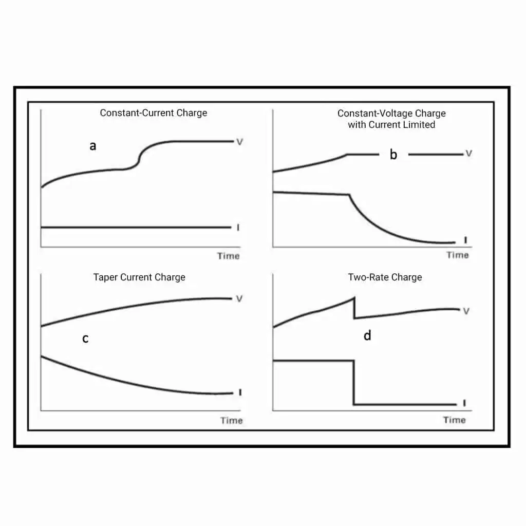
- Two-stage current and voltage limited charging
Another popular charge profile is shown in Fig. 1d. With this, the voltage is allowed to rise in the bulk phase until it reaches the gassing voltage. The current then drops to a low fixed level to reduce the voltage which gradually rises to the gassing level. Generally, there is a time cut-off linked to the initial bulk phase charging time. This enables a fixed gassing period and a fixed ampere-hour input based on the battery’s state of charge
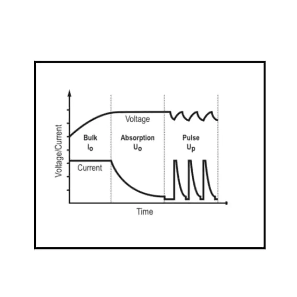
- Voltage limited bulk charging with equalising constant current pulse.
Fig. 2 is a representation of a common pulse charging method. This is generally of benefit to users of VRLA batteries who have a limited time to fully recharge their batteries. In this method, there is both a CC and CV phase where the bulk of the charge is applied.
- The pulse is generally a 10 to 20-second current burst with voltage restriction followed by a pause of up to a couple of minutes. Because the voltage lags behind the current, which has a limited duration, it does not reach peak levels before dying down. In this way, the gas evolution is restricted and the pause time between the current pulses allows the gases to recombine to water, preventing dry-out.
The comments so far have been aimed at lead-acid batteries. Charging of Li-ion, NiCd and NiMH batteries requires different battery charging algorithms to that of a lead-acid battery. Starting with Lithium-ion battery the immediate point to note is that there are different charging voltages for different Li-ion cathodes. A Lithium-ion -FePO4 operates at 3. 2V per cell whilst a Li-Co is 4.3v per cell. This means you cannot use the same charger for both of these batteries.
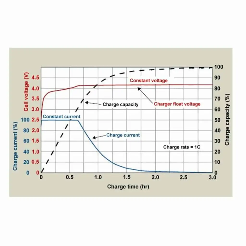
However, the general principle is the same for all types of lithium-ion batteries and quite different from a lead-acid battery. Because there is no chemical reaction during the charge and discharge processes, the transfer is fast at very high rates limited by the charger output or the BMS (Battery Management System). Typically, between 0.1C and 1C rates at constant current with a voltage cut-off are common. Fig 3 shows a typical charging profile for a li-ion cell. The charging period can also be ended when a minimum current is reached around 2-3% of the 1C ampere value.
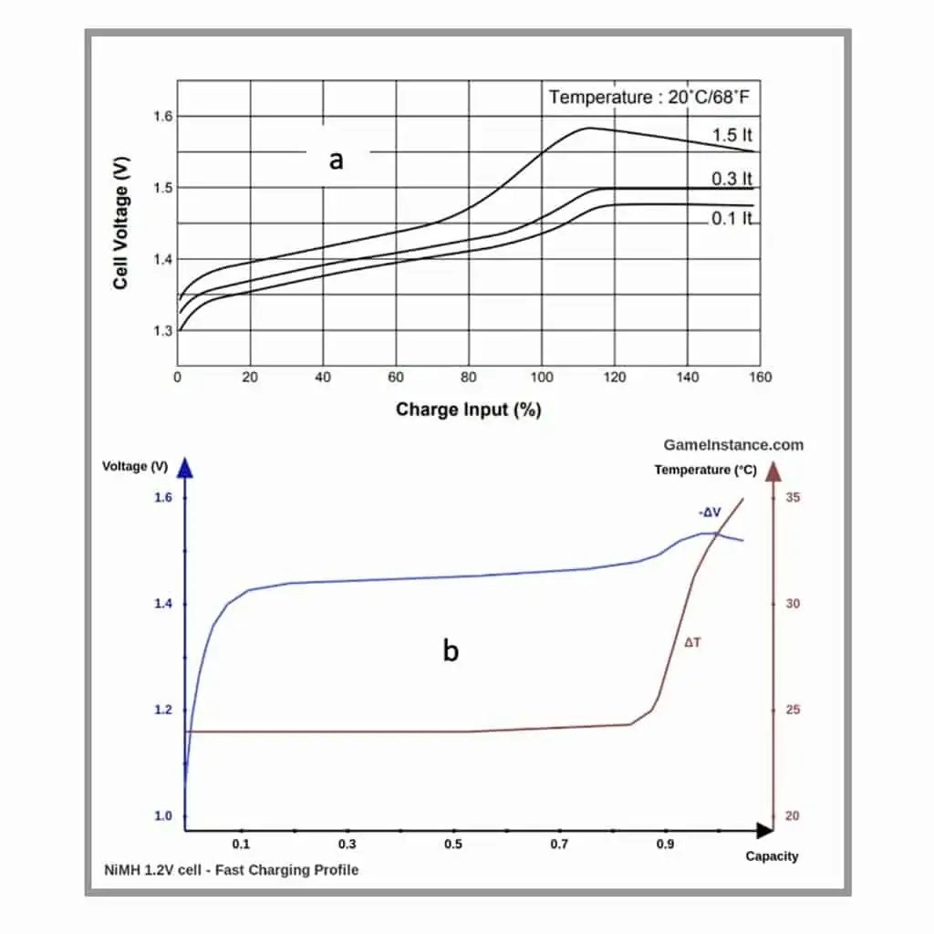
NiMH and NiCd also have different charging patterns and very different responses to charging, both to other chemistries and also to each other. Fig 4 shows a typical charging pattern for both Ni-Cad (a) and NiMH (b). Although both nickel variants have the same rest and operating voltage, the on-charge voltage can vary considerably. A charger for both types cannot rely on voltage as a charge termination mechanism. For this reason, chargers simply use a one or two-stage constant current charger with a termination based on time, voltage slope and temperature change of slope. Examination of the charge characteristics shows that there is both temperature rise and simultaneous voltage response drop as the charge reaches 100% completion.
These characteristics are used to determine the end of charge. Since the absolute voltage varies with temperature and is different for both types of cell. The onset of the negative voltage slope (-dV/dt) or the rapid temperature slope increase (dT/dt), are the characteristics most commonly used. If a timing method is used then the current should be very low to prevent overcharge and oxygen loss. In some cases, particularly with cells or batteries out of balance, it is best to discharge to 0.9-1.0 volts per cell before charging using the timer method.
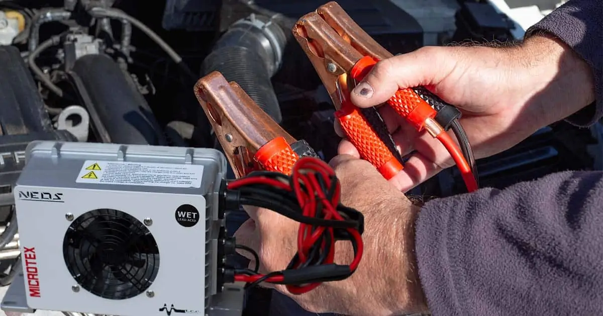
How does a battery charger work?
All chargers draw Alternating Current (AC) grid power and convert it to Direct Current. In the process, there will be some AC ripples that need to be kept to less than 3%. Some of the battery chargers in the market have features to filter the ripples, which would otherwise harm the battery during charging. In any case, it is better to use 3 phase supply since the single-phase current has a 10 % ripple.
All chargers draw Alternating Current (AC) grid power and convert it to Direct Current. In the process, there will be some AC ripples that need to be kept to less than 3%. Some of the battery chargers in the market have features to filter the ripples, which would otherwise harm the battery during charging. In any case, it is better to use 3 phase supply since the single-phase current has a 10 % ripple.
Constant voltage charger
Constant voltage allows the full current of the battery charger to flow into the battery until the power supply reaches its preset voltage. The current will then taper down to a minimum value once that voltage level is reached. The battery can be left connected to the battery charger until ready for use and will remain at that “float voltage”, trickle charging to compensate for normal battery self-discharge.
Constant voltage constant current
Constant voltage / constant current (CVCC) is a combination of the above two methods. The charger limits the amount of current to a pre-set level until the battery reaches a preset voltage level. The current then reduces as the battery becomes fully charged. The lead-acid battery uses the constant current constant voltage (CC/CV) charge method. A regulated current raises the terminal voltage until the upper charge voltage limit is reached, at which point the current drops due to saturation.
Different types of battery chargers
Existing battery charging technology relies on microprocessors (computer chips) to recharge, using 3 steps of regulated charging. These are the “smart chargers”. These are readily available. The three steps in lead-acid battery charging are the main current inputs for conversion, and float charge on a continuous period. Periodic equalization charge to maintain uniformity is necessary. Use the battery manufacturer’s recommendations on charging procedures and voltages or a quality microprocessor controlled charger to maintain battery capacity and service life.
The “smart chargers” are profiled with contemporary charging technology in mind, and also take information from the battery to provide maximum charge benefit with minimum observation.
VRLA – Gel and AGM batteries require different voltage settings. This is to avoid gassing and dry-out. The oxygen recombination process in a Valve Regulated Lead-acid (VRLA) battery requires a lower voltage setting to avoid hydrogen evolution and cell dry-out.
The maximum charging voltage for Gel batteries is 14.1 or 14.4 volts, which is lower than a wet or AGM VRLA type battery needs for a full charge. Exceeding this voltage in a Gel battery can cause bubbles in the electrolyte gel and permanent damage.
The current rating for battery chargers recommends sizing the charger at a maximum current of 25% of the battery capacity. Some batteries specify 10% of capacity It is safer to use a lower current, although it takes longer.
A constant current – constant voltage (CCCV) charge method is a good option. A constant current increases the terminal voltage until the upper charge voltage limit is reached, at which point the current drops due to saturation. The charge time is 12–16 hours and longer (36 hours) for large stationary batteries. The lead-acid battery is slower and cannot be charged as quickly as other battery systems. With the CCCV method, lead-acid batteries are charged in three steps, [1] constant-current charge, [2] Constant voltage and [3] float charge on completion of charge.
The constant-current charge applies the bulk of the charge and takes up roughly half of the required charge time; the topping charge continues at a lower charge current and provides saturation, and the continuous float charge compensates for the loss caused by self-discharge. During the constant-current charge, the battery charges to about 70 percent in 5–8 hours; the remaining 30 percent is filled with Constant Voltage that lasts another 7–10 hours. The float charge in the third step maintains the battery at full charge.
Battery charging, can you overcharge your 12V battery?
In all of these chemistries overcharging can create damage or safety risks. In the case of lead acid batteries, overcharge voltages are limited and excess current is dissipated in the breakdown of water, hydrogen and oxygen release and the creation of heat. Increasing current will not increase the voltage, it will increase the gassing and water loss rate and cause a temperature rise. Some overcharge is tolerated particularly when the cell or battery equalisation is required.
For lithium-ion batteries, overcharge is difficult due to the BMS incorporated in the battery. This will cut off the current supply once the termination voltage is reached, or the temperature becomes too high. This is a necessary precaution as li-ion cells contain a volatile electrolyte which will be released at higher temperatures. It is the vapour from the electrolyte which catches fire in li-ion batteries making overcharge very dangerous. NiCad and NiMH batteries should not be overcharged as they will lose oxygen and therefore electrolyte, even if they are the sealed versions.
There are several indicators of a battery’s SOC: the rest voltage measured at its terminals, the specific gravity of the electrolyte (flooded open batteries) or the impedance value. They are different for each battery chemistry, and for this reason, it is best to look at each type separately:
1. Lead-acid.
Specific gravity.
The reaction of the plates with sulphuric acid on charge and discharge determines the ratio of acid to water in a cell.
When charged the concentration of sulphuric acid is high, when discharged it is lower (eq. 1). Because the density of acid is 1.84 and that of water is 1 the specific gravity, SG of the electrolyte increases on charging and decreases on discharging.
The reaction has a first-order relationship which means the change in concentration is linear so measurement of the SG gives a direct indication of the SOC of the battery, Fig. 5.
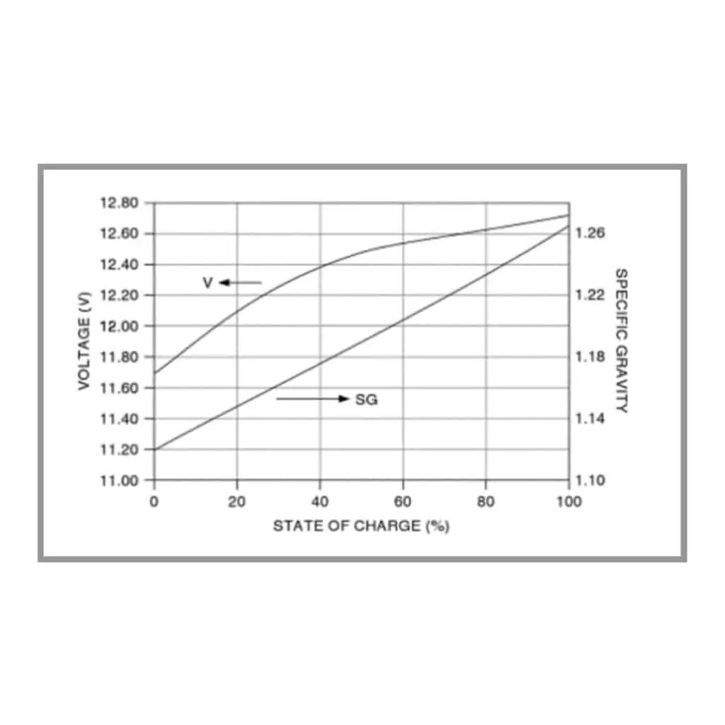
One note of caution: this does not apply when the battery charging is in progress and in the bulk, or pre-gassing phase. Without electrolyte stirring, the denser acid produced on charge will sink, leaving the bulk of the electrolyte more dilute until a voltage of 2.4 volts per cell is reached. From this point, gas evolved at the plates will create a stirring action to mix the acid.
Rest voltage: This can be an indication of SOC and related to the specific gravity of the cell in the following relationship:
- Rest volts = SG + 0.84 …………………………………………………………..eq 2
As an example, a 2V cell with a specific gravity of 1.230 will have a rest voltage of 1.230 + 0.84 = 2.07 volts
Using this relationship can give a reasonably accurate indication of the battery SOC, however, different batteries have different operating ranges for SG and so the top of charge condition of a VRLA SG could be 1.32 compared to an OPzS with a top SG of 1.28. Temperature also affects the SG and therefore the cell voltage. The effect of temperature on open circuit voltage is given in Table 2.
Another factor is that freshly charged batteries have a high concentration of acid next to the plates due to the formation of sulphuric acid on a charge. This is why the voltage after charging remains high for some time perhaps up to 48 hours before settling at a consistent value. Unless a short discharge is made to the battery then it has to rest to allow equalisation of the acid concentration before taking a voltage reading.
Tools needed for SOC measurement
These consist of a DC voltmeter or a multimeter for the voltage measurements and a hydrometer for the specific gravity reading.
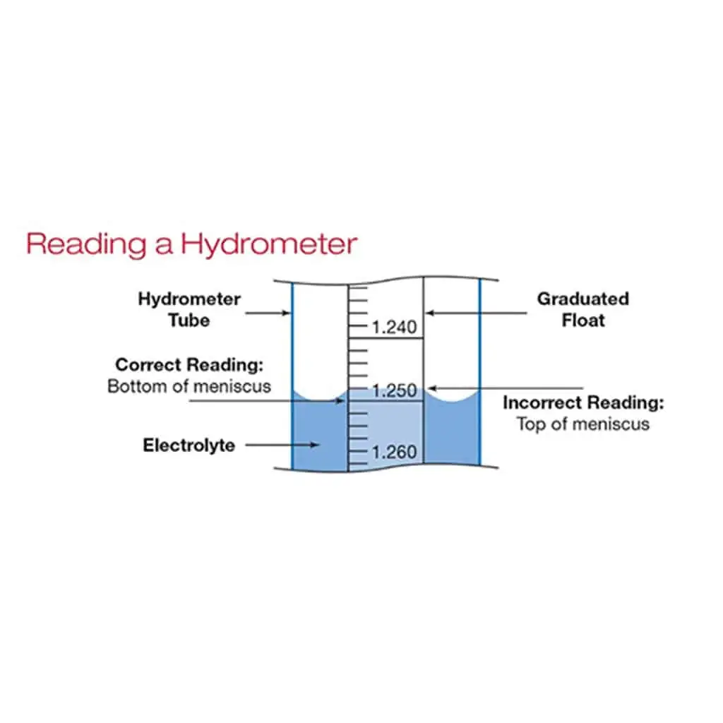
For flooded cells, other than a discharge test, the hydrometer is the best method of determining the state of charge. Use of a hydrometer does take some practice and should be done very carefully. The procedure is to place the battery in a suitable position so that the hydrometer reading can be taken at eye level (Fig. 6 above).
For sealed batteries, it is not possible to use a hydrometer so a measurement of the rest volts is the only option. This method is applicable to both sealed and flooded lead acid batteries.
For this, the multimeter should be set at an appropriate maximum voltage to ensure it can read more than 12 volts, but also produce at least 2 decimal places of accuracy. Using eq. 2, the voltage can be used after temperature adjustment, to estimate the SG and therefore the SOC of the battery, provided the manufacturer’s SG value for the fully charged battery are known.
In both cases of using voltage or a hydrometer to measure State-of-charge, SOC, it is necessary to apply a temperature compensation. Table 2, supplied by the BCI, gives the appropriate adjustments for both hydrometer and voltage meter readings.
Table 2 Compensation for electrolyte Specific Gravity and voltage readings with temperature
| Electrolyte Temperature Fahrenheit (°F) | Electrolyte Temperature Celsius (°C) | Add or Subtract to Hydrometer's SG Reading | Add or Subtract to Digital Voltmeter's Reading |
|---|---|---|---|
| 160° | 71.1° | +.032 | +.192 V |
| 150° | 65.6° | +.028 | +.168 V |
| 140° | 60.0° | +.024 | +.144 V |
| 130° | 54.4° | +.020 | +.120 V |
| 120° | 48.9° | +.016 | +.096 V |
| 110° | 43.3° | +.012 | +.072 V |
| 100° | 37.8° | +.008 | +.048 V |
| 90° | 32.2° | +.004 | +.024 V |
| 80° | 26.7° | 0 | 0 V |
| 70° | 21.1° | -.004 | -.024 V |
| 60° | 15.6° | -.008 | -.048 V |
| 50° | 10° | -.012 | -.072 V |
| 40° | 4.4° | -.016 | -.096 V |
| 30° | -1.1° | -.020 | -.120 V |
| 20° | -6.7° | -.024 | -.144 V |
| 10° | -12.2° | -.028 | -.168 V |
| 0° | -17.6° | -.032 | -.192 V |
2. Li-ion, NiMH and NiCd.
For all of these chemistries, SOC measurement presents serious challenges. All have a very flat discharge curve with a very small voltage difference between the fully charged and the discharged state. The charge-discharge reactions within NiCd and NiMH cells do not appreciably alter the SG of the electrolyte and all Li-ion chemistries operate with completely sealed cells. This makes static or random spot checks on a battery in service almost impossible, certainly for a non-professional user. The current state of the art State-of-charge, SOC measurements for these chemistries are based on dynamic readings taken during their operation.
They can be based on ampere-hour count, voltage response to discharge currents or even constant current pulses. Measuring equipment is usually built into expensive or sophisticated devices such as electric vehicles or industrial machines, where it is necessary to know the available run time. In less sophisticated equipment such as hand power tools, noticing the tool stopping or running less quickly is the only indication available.
There are commercially available impedance spectrometer testers available which measure the internal impedance of a battery to predict its state of charge. These devices depend upon an algorithm based on testing hundreds of batteries in various states of charge and of various ages to predict the SOC. The results are specific to a particular battery’s chemistry and age. The more tests which have been done to make the algorithm the more accurate the algorithm.
While battery charging, can you overcharge a battery?
However, you decide to measure the state of charge there are rules which apply to all types of battery. These are to prevent over-discharge of a battery which may cause individual cells to be damaged by causing them to go into reverse, even to have negative voltages. Overcharging is less clear-cut as in the case of lead acid it is sometimes necessary to do this to equalise cells or individual batteries in a bank. However, excessive overcharge leads to gassing with water loss and corrosion of the positive plates both of which reduce battery life.
For Nickel based batteries water loss is the most common problem again leading to reduced operating life. In the case of lithium chemistries, it is usually impossible to overcharge due to the incorporated BMS which automatically cuts off the current input at a pre-set voltage. In some designs, there is an inbuilt fuse which prevents overcharge. However, this usually makes the battery irreversibly inoperable.
Battery charging, overcharge how do you avoid it?
The decision to recharge a battery depends on the circumstances of use and the degree of the discharge. As a general rule for all chemistries the battery should not go below 80% DOD in order to maximise its operating life. This means that the final SOC of the battery should be calculated from the point of measurement to the end of its daily operation. If for example the SOC is 40% at the beginning of the operation and it will use 70% of its capacity by the end of the operation then the battery should be recharged before allowing it to continue.
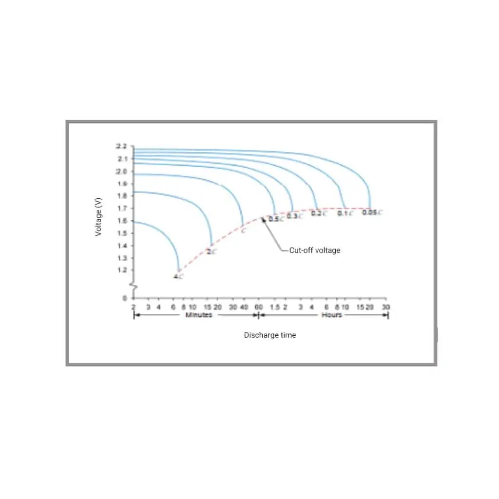
To make this decision its necessary to determine the remaining capacity or run time left in a battery. This is not straightforward as battery capacity is determined by the discharge rate. The higher the discharge rate, the less capacity that is available. Lead acid batteries are very susceptible to this, as shown in Fig.8.
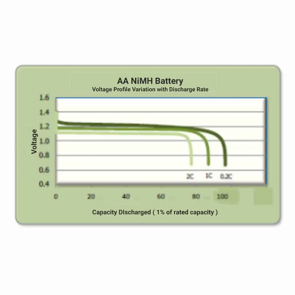
Li-ion and NiCd based batteries do have reduced capacities at higher discharge rates but they are not as pronounced as lead acid. Fig. 9 shows the effect of 3 different discharge rates on the available capacity of a NiMH battery. In this case, 0.2C (5 hour rate), 1C (1 hour rate) and 2C (1/2 hour rate).
In all cases the voltage profile stays very flat but at a reduced level until the end of the discharge period when the voltage suddenly collapses.
Battery charging - calculation of battery charge & discharge times
Calculation of battery charging and discharge times
To establish the discharge time for any battery in a particular state of charge, the current drawn and the battery capacity at a particular discharge rate must be known. The operating time can be roughly calculated by using a rule of thumb for each battery chemistry.
Knowing the effective capacity at a particular discharge rate will enable the run time to be predicted as follows:
Standard capacity of battery (amp hours) = C
Discharge current (amps) = D
Discharge factor = D/C = N
Discharge rate (amps) = NC
Capacity at discharge rate D (amp hours) = CN
Discharge time for a fully charged battery (hours) = CN /D
Using the estimation of the state of charge as a percentage, the run time can be calculated:
Run time = % state of charge x CN /(100xD) = hours
Calculation of the charge time is complex as it depends upon the state of charge of the battery, the battery type, the output of the charger and the charger type. It is necessary to know the state of charge of the battery to determine the ampere-hours which need to be put into the battery to recharge it. The rate at which this happens depends on the charger rating and how it charges. Clearly a li-ion battery can recharge in a couple of hours from completely flat if the charger has sufficient output.
A sealed lead-acid battery with limitation on the charger output will take much longer due to the voltage restriction and reduced current in the gassing phase. Once the state of charge is determined you can calculate how many ampere-hours are needed to be put back into the battery. Knowing the charger characteristics will help to make the time calculation based on the rate at which it will charge bearing in mind the charging pattern used.
Another factor is the ambient temperature (weather conditions) which affects the on-charge voltage and the current drawn by the charger. Higher temperatures will drop the charging voltage but also increase the current drawn. For batteries on float charge, it is necessary to apply a voltage compensation with temperature. Microtex can advise on the adjustment required where temperatures vary significantly from the standard 25°C.
Final words about battery charging!
Correct battery charging and knowing its state of charge is not straightforward. Often batteries are purchased with no advice or backup service from the vendor. That is why it is important to buy from a reputable supplier who puts customer satisfaction first. For advice on any battery charging maintenance or installation, the best course of action is to contact a professional trusted supplier.
As always, Microtex, a long-standing international battery manufacturer with a faultless customer satisfaction record is always on hand to help. They are one of the few companies who have the knowledge and the products to supply and service batteries for practically all industrial and consumer applications. If your battery charging lets your battery down, contact the people who won’t.
For all battery charging, matters get in touch with Microtex.